
Major-minor cylinder combined rotor engine

A technology combining rotors and engines, applied in rotary piston engines, rotary or oscillating piston engines, combustion engines, etc., can solve the problems of increased fuel and oil consumption, long flame propagation path, large fuel consumption, etc., and achieve pollutant emissions. The effect of reducing the amount of waste, reducing pollutant emissions, and reducing fuel consumption

Inactive Publication Date: 2009-08-19
孙国繁
View PDF0 Cites 2 Cited by
  • Summary
  • Abstract
  • Description
  • Claims
  • Application Information

AI Technical Summary

Problems solved by technology

[0002] The engine widely used at present is a reciprocating piston engine. If it is a gasoline engine, it also includes an ignition system, and if it is a supercharged engine, it also includes a supercharging system. This machine has many components and a complex structure, which not only has high manufacturing costs, but also has a large mechanical loss; Each cylinder performs a working cycle of "intake → compression → work → exhaust". This cycle leads to low effective thermal efficiency, high fuel consumption, and high emissions of harmful substances such as carbon dioxide.
On the basis of traditional technology, multi-valve and overhead camshaft, turbocharging, variable valve timing and dual spark plugs, in-cylinder direct injection and variable intake manifold length, electronically controlled common rail direct Modern technologies such as fuel injection have improved thermal efficiency, reduced fuel consumption and emissions of harmful substances such as carbon dioxide. However, due to the intermittent combustion of fuel in the internal combustion engine, and each combustion cycle is very short, each combustion cycle It is difficult to achieve the complete combustion of fuel, which will inevitably lead to the discharge of non-combustion and partially combusted fuel from the internal combustion engine, which makes the thermal energy efficiency of the fuel far from the theoretical value, and the pollutant ratio in the exhaust gas is quite high
[0003] A small amount of triangular rotor engines are used. The combustion chamber of this engine is not conducive to complete combustion, and the flame propagation path is long, which increases the consumption of fuel and engine oil, and emits more harmful substances such as carbon dioxide; this engine has high manufacturing technology, high cost, and difficult promotion.

Method used


Image

  • Major-minor cylinder combined rotor engine
  • Major-minor cylinder combined rotor engine
  • Major-minor cylinder combined rotor engine

Examples


Embodiment Construction

[0025] The present invention will be further described below in conjunction with accompanying drawing:

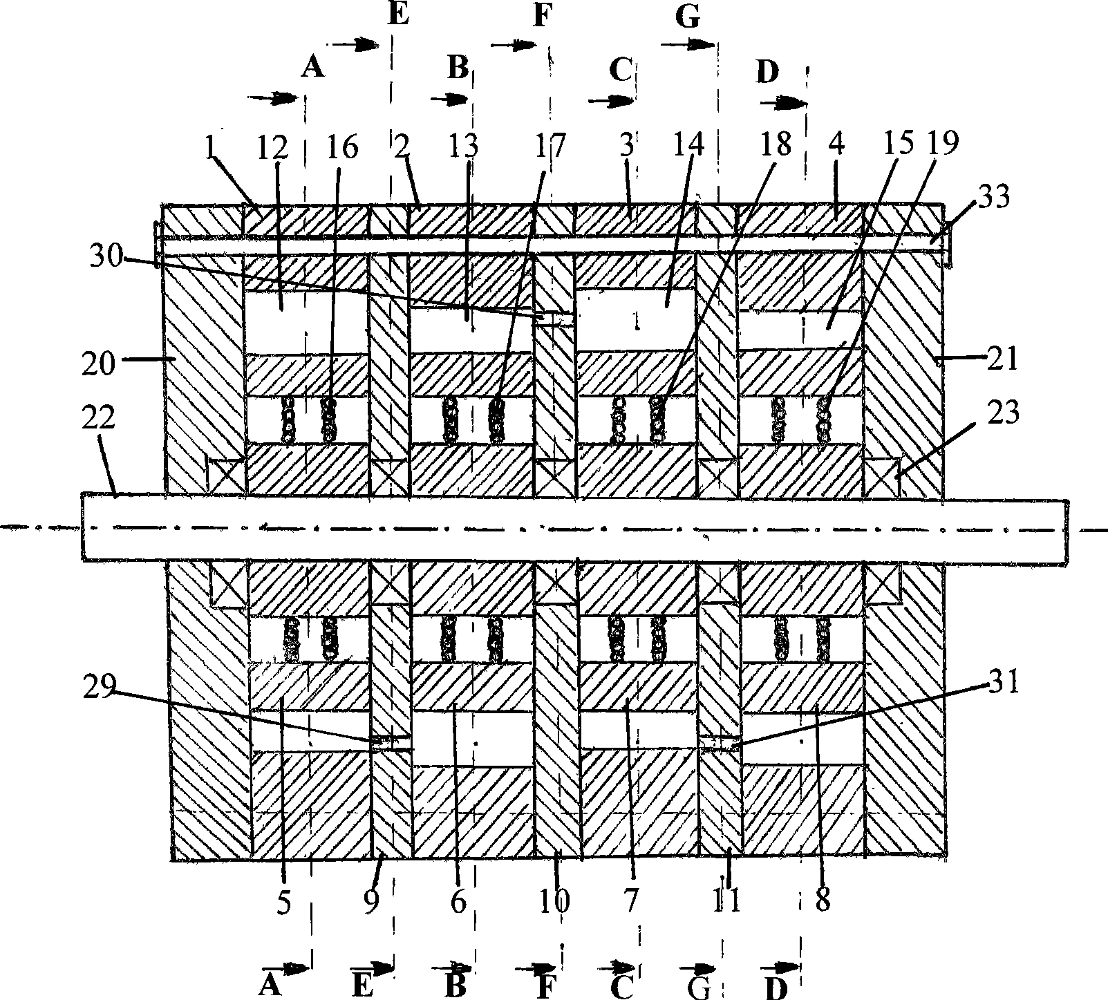
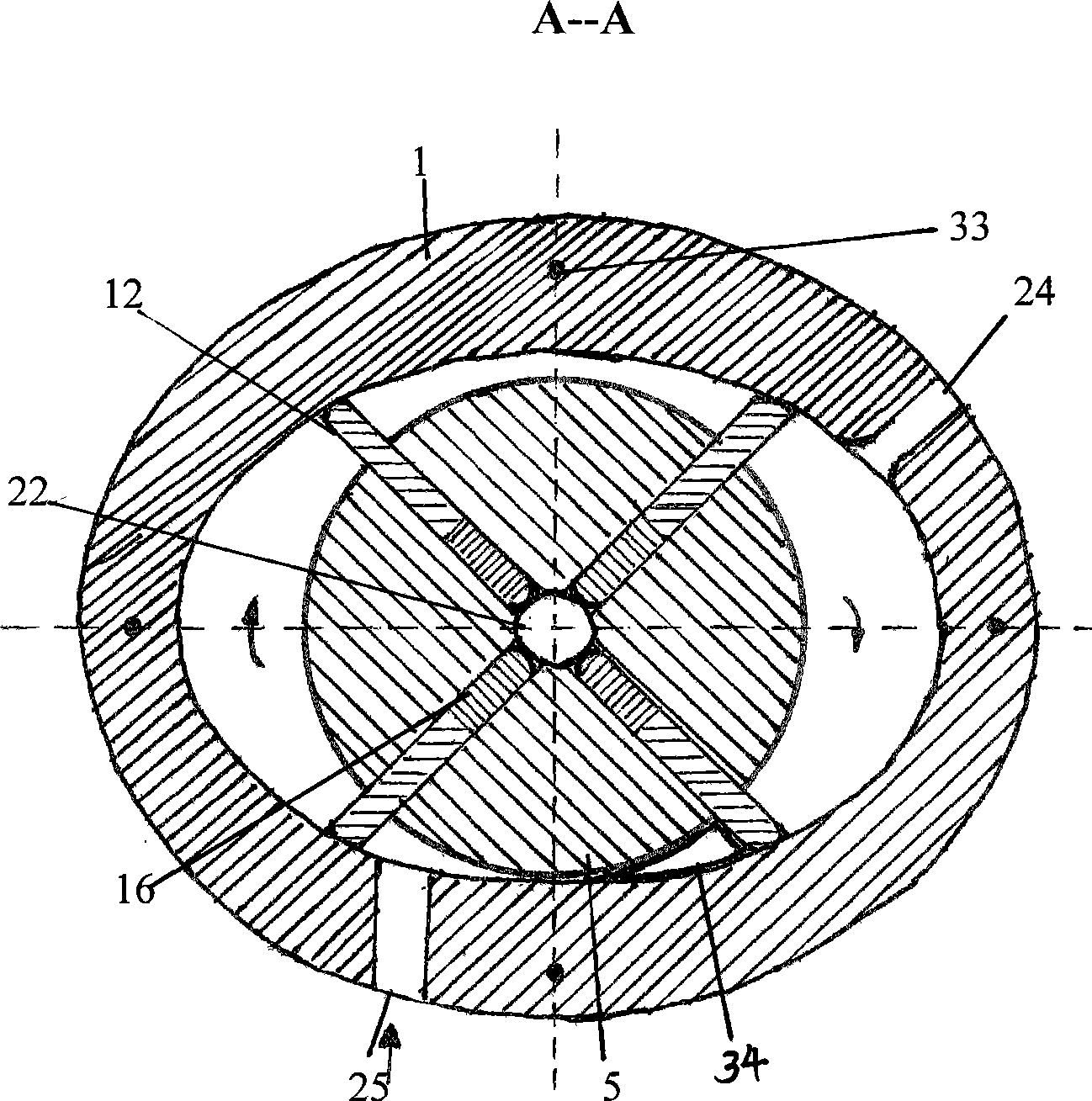
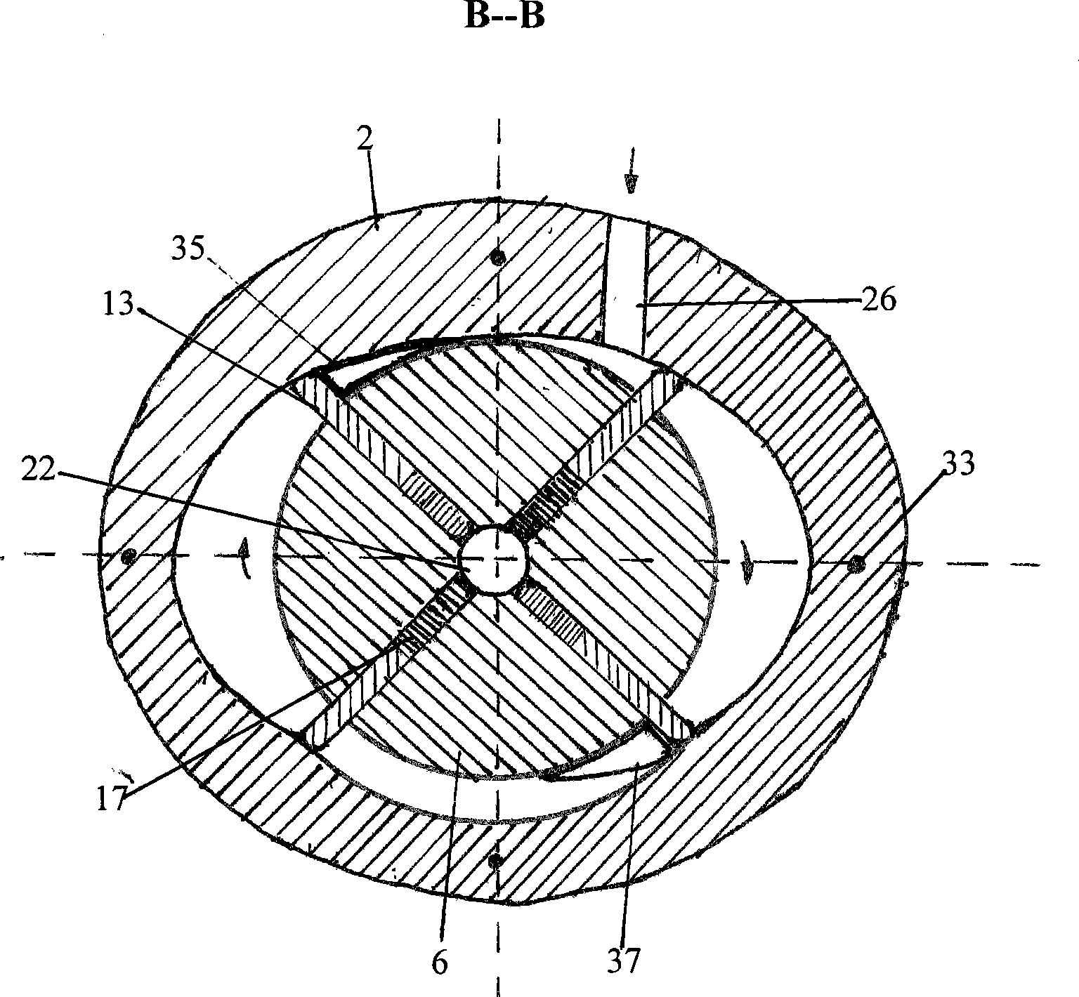
[0026] The embodiment of the present invention is that a master cylinder and three auxiliary cylinders are combined into a cylinder group engine. attached figure 1 to attach Figure 8As shown, the main and auxiliary cylinder combined rotor engine of the present invention is composed of main cylinder 1, auxiliary cylinder 2, 3, 4, rotor 5, 6, 7, 8, dividing plate 9, 10, 11, slide plate 12, 13, 14, 15 , Springs 16, 17, 18, 19, end caps 20, 21, shaft 22, bearing 23, spark plug 24 and the like. The inner cavities of the main cylinder 1 and the auxiliary cylinders 2, 3, and 4 are elliptical cylindrical, and the partitions 9, 10 are used between the main cylinder 1 and the auxiliary cylinder 2, the auxiliary cylinder 2 and the auxiliary cylinder 3, and the auxiliary cylinder 3 and the auxiliary cylinder 4. , 11 isolation, main cylinder 1, auxiliary cylinder 2, 3, 4 are coaxial...


PUM


Abstract

The invention relates to a master-auxiliary cylinder composite rotor engine which is composed of a master cylinder, auxiliary cylinders, a rotor, a baffle plate, a slide plate, a spring, an end cover, a shaft, a bearing, a spark plug, etc. Fuel and other mixed gas are poured into the master cylinder of the engine to combust for working, then the incompletely combusted high-temperature high-pressure gas is discharged into one or plural auxiliary cylinders for continual combustion working, and then is discharged into the air after combustion working in the last auxiliary cylinder. Compared with the prior internal combustion engine, the invention has the obvious following advantages in working circulation: 1, reducing the fuel consumption; 2, improving the effective thermal efficiency; 3, improving the performance per liter; 4, reducing pollutants discharge; and 5, reducing manufacture cost due to structure simplification.

Description

technical field [0001] The invention relates to an engine, in particular to a combined rotor engine with main and auxiliary cylinders. Background technique [0002] The engine widely used at present is a reciprocating piston engine. If it is a gasoline engine, it also includes an ignition system, and if it is a supercharged engine, it also includes a supercharging system. This machine has many components and a complex structure, which not only has high manufacturing costs, but also has a large mechanical loss; Each cylinder performs a work cycle of "air intake→compression→work→exhaust". This cycle leads to low effective thermal efficiency, high fuel consumption, and high emissions of harmful substances such as carbon dioxide. On the basis of traditional technology, multi-valve and overhead camshaft, turbocharging, variable valve timing and dual spark plugs, in-cylinder direct injection and variable intake manifold length, electronically controlled common rail direct Modern...

Claims


Application Information

Patent Timeline
IPC IPC(8): F02B53/02F02B55/08F02B55/16F01C1/344
CPCY02T10/17Y02T10/12
Inventor 孙国繁
Owner 孙国繁
Learn More