Power management system
A technology of power management system and system power supply, which is applied in the direction of control/regulation system, collector, electric vehicle, etc., and can solve problems such as unmaintainable input power supply, low input power supply voltage signal, and system failure
- Summary
- Abstract
- Description
- Claims
- Application Information
AI Technical Summary
Problems solved by technology
Method used
Image
Examples
Embodiment 1
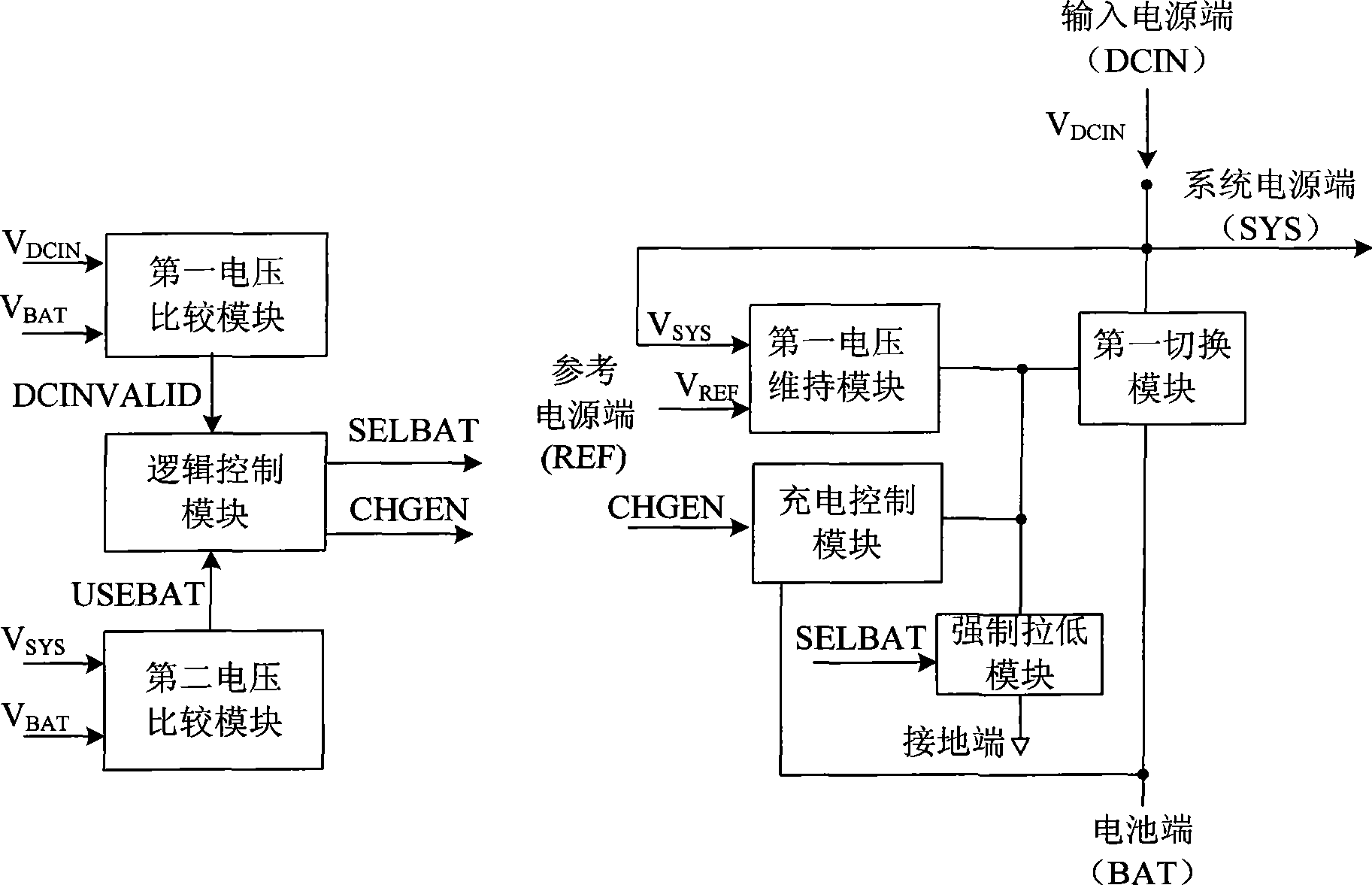
[0023] The power management system proposed in this embodiment includes: an input power supply terminal, a battery terminal, a system power supply terminal, a ground terminal, a reference power supply terminal, a first voltage maintaining module, a first switching module, a charging control module, a forced pull-down module, a second A voltage comparison module, a second voltage comparison module and a logic control module.
[0024] Wherein, for the convenience of description, the input power terminal is called DCIN, the battery terminal is called BAT, the system power terminal is called SYS, and the reference power terminal is called REF. Correspondingly, the input power terminal voltage signal is called V DCIN , the battery terminal voltage signal is called V BAT , the system power supply terminal voltage signal is called V SYS , the reference power supply terminal voltage signal is called V REF .
[0025] In this power management system, the first voltage maintenance mo...
Embodiment 2
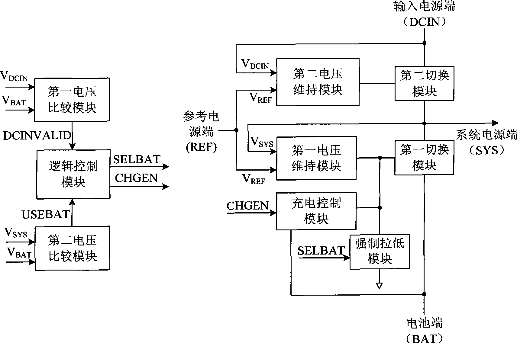
[0036] In the prior art, when the system consumes the current signal, the charging current signal and the sum of the two, any one of these is greater than the current signal provided by the input power supply, the voltage signal of the input power supply terminal will not be maintained, and if this input power comes from USB port, it will violate the USB specification, resulting in USB connection interruption.
[0037] The system power terminal receives the voltage signal of the input power terminal, and the connection relationship includes two ways:
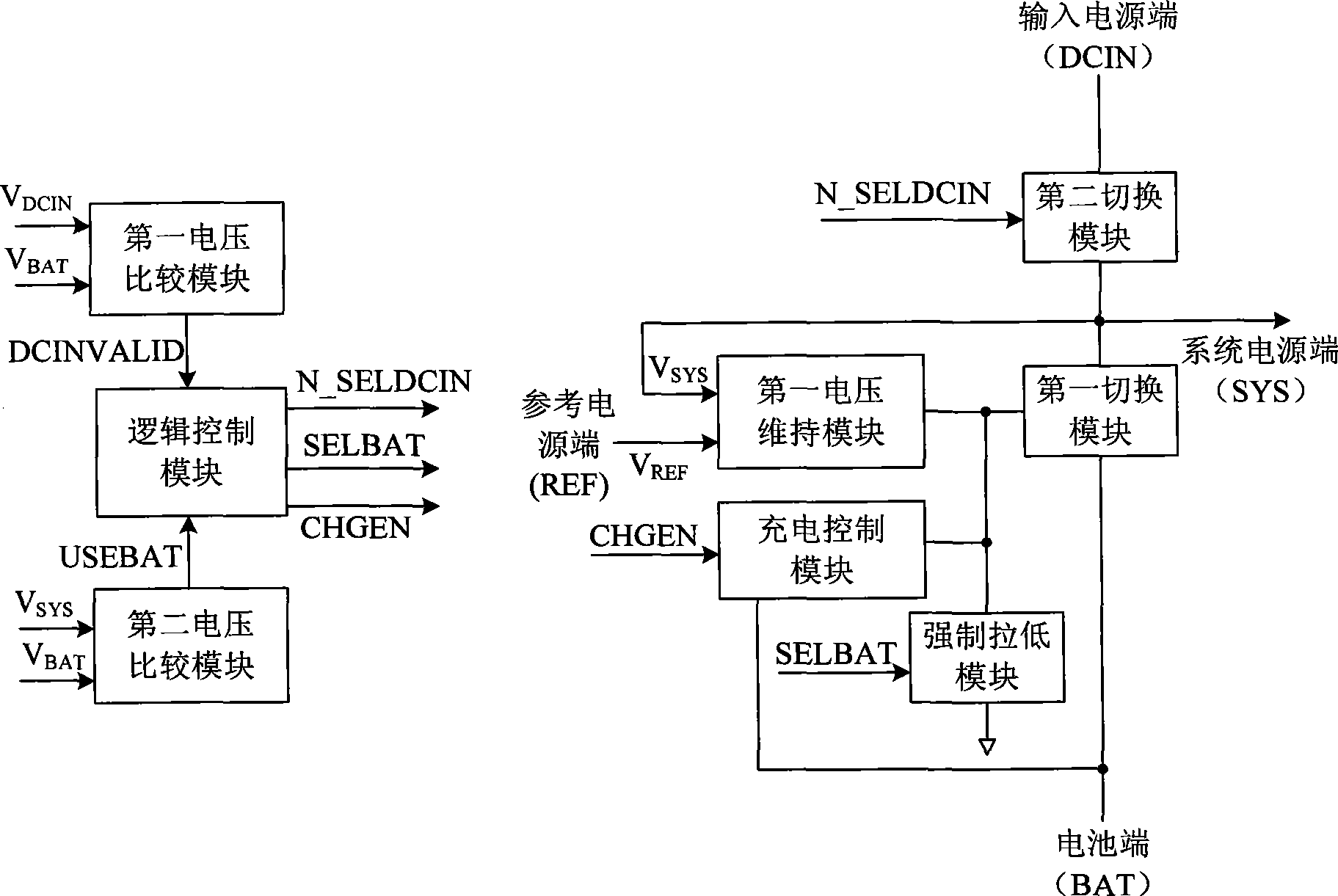
[0038] The first way: on the basis of the power management system proposed in Embodiment 1, a second switching module is also included. The input power supply terminal, the second switching module and the system power supply terminal are sequentially connected; the logic control module outputs a fourth control signal to the second switching module according to the received power supply connection signal, such as figure 2 as sh...
Embodiment 3
[0047] As a further improvement of Embodiment 1 above, the first differential amplifier further includes an enabling terminal, which receives the enabling signal generated by the logic control module according to the received power supply connection signal and battery connection signal.
[0048] Figure 7 It is a schematic diagram of a specific implementation of an integrated circuit including the last stage circuit of the first voltage maintenance module, the last stage circuit of the charging control module, the first switching module and the forced pull-down module. The integrated circuit includes a current source, a second Three PMOS transistors, a fourth PMOS transistor, a first PMOS transistor and an NMOS transistor. Wherein, the third PMOS transistor represents the last stage output circuit of the first voltage maintaining module, and the fourth PMOS transistor represents the last stage output circuit of the charging control module. In this embodiment, the current supp...
PUM
 Abstract
Description
Claims
Application Information
 - Generate Ideas
- Intellectual Property
- Life Sciences
- Materials
- Tech Scout
- Unparalleled Data Quality
- Higher Quality Content
- 60% Fewer Hallucinations
Browse by: Latest US Patents, China's latest patents, Technical Efficacy Thesaurus, Application Domain, Technology Topic, Popular Technical Reports.
© 2025 PatSnap. All rights reserved.Legal|Privacy policy|Modern Slavery Act Transparency Statement|Sitemap|About US| Contact US: help@patsnap.com


