


Quick Research
Generate reliable direction feasibility study reports for your R&D in just a few steps.

Technical Q&A
Discover and master advanced knowledge NOW. Basics, ideas, possibilities, all at once.

Find Solutions
As an expert in R&D theories, this can generate solutions to your technical problems instantly.

Evaluate Feasibility
Analyze your overall solution with one click, know your potential R&D risks in advance.

Monitor Landscape
Get weekly tech updates, stay abreast of the latest tech innovations and key insights.
Preparation of solid thermoluminescent dosemeter material
A thermoluminescent dose and solid technology, which is applied in the field of preparation of solid thermoluminescent dosimeter materials, can solve the problems of reduced thermoluminescent sensitivity, complex peak shape of thermoluminescent light, unfavorable dose signal testing, etc., and achieve production cost Inexpensive, stable chemical properties of the product, easy to test the effect of the signal
- Summary
- Abstract
- Description
- Claims
- Application Information
AI Technical Summary
Problems solved by technology
Method used
Image

Examples
Embodiment 1
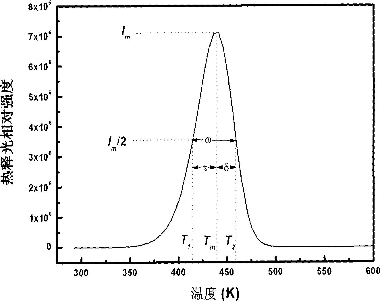
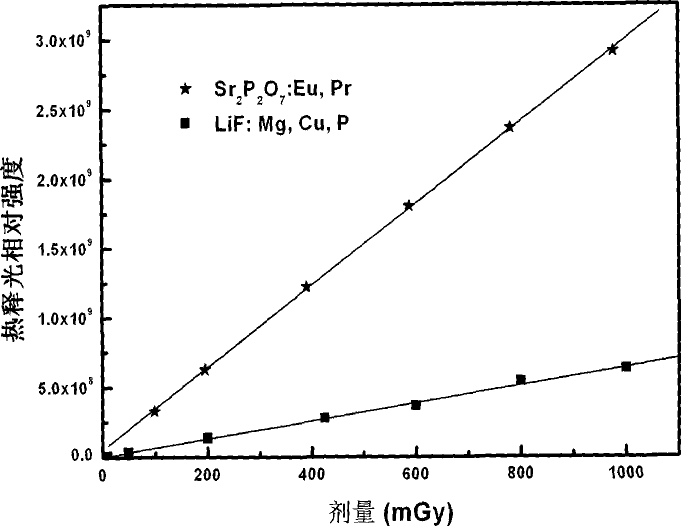
[0014] Raw material is SrHPO 4 (analytical pure), NH 4 h 2 P0 4 (analytical pure), Eu 2 o 3 (99.99%), Pr 6 o 11 (99.99%) The molar ratio between them is 1:0.05:0.02:0.02. Grind the raw materials evenly in a mortar, dry them, put them into a corundum crucible, and then put them into a large corundum crucible, filled with carbon Rods were put into a high-temperature furnace at 900°C for 3 hours, cooled to room temperature naturally, taken out and ground to obtain samples. The obtained product is a white powder, and its thermoluminescence peak is as figure 1 As shown, its luminescence curve is a single peak, and the peak temperature is at 439.5K.
Embodiment 2
[0016] Raw material is SrHPO 4 (analytical pure), NH 4 h 2 PO 4 (analytical pure), Eu 2 o 3 (99.99%), Pr 6 0 11 (99.99%) The molar ratio between them is 1:0.05:0.001:0.08. Grind the raw materials evenly in a mortar, dry them, put them into a corundum crucible, and then put them into a large corundum crucible, filled with carbon Rods were put into a high-temperature furnace for 3 hours at 1000°C and baked for 3 hours, cooled to room temperature naturally, taken out and ground to obtain samples. The obtained product is a white powder, and its thermoluminescence peak is as figure 1 As shown, its luminescence curve is a single peak, and the peak temperature is at 439.5K.
Embodiment 3
[0018] The raw materials are SrHPO4 (analytical pure), NH 4 h 2 PO 4 (analytical pure), Eu 2 o 3 (99.99%), Pr 6 o 11 (99.99%) The molar ratio between them is 1: 0.05: 0.005: 0.001. Grind the raw materials evenly in a mortar, dry them, place them in a corundum crucible, and then put them into a large corundum crucible, filled with carbon Rods were put into a high-temperature furnace at 1200°C for 5 hours, cooled to room temperature naturally, taken out and ground to obtain samples. The obtained product is a white powder, and its thermoluminescence peak is as figure 1 As shown, its luminescence curve is a single peak, and the peak temperature is at 439.5K.
PUM
 Abstract
Description
Claims
Application Information
 - R&D Engineer
- R&D Manager
- IP Professional
- Industry Leading Data Capabilities
- Powerful AI technology
- Patent DNA Extraction
Browse by: Latest US Patents, China's latest patents, Technical Efficacy Thesaurus, Application Domain, Technology Topic, Popular Technical Reports.
© 2024 PatSnap. All rights reserved.Legal|Privacy policy|Modern Slavery Act Transparency Statement|Sitemap|About US| Contact US: help@patsnap.com