
Real-time monitoring device for light exposure in holographic grating production

A real-time monitoring and holographic grating technology, applied in the field of spectroscopy, can solve the problems of inconvenient operation, difficult diffracted light, weak diffracted light energy, etc.

Inactive Publication Date: 2009-05-13
CHANGCHUN INST OF OPTICS FINE MECHANICS & PHYSICS CHINESE ACAD OF SCI
View PDF1 Cites 13 Cited by
  • Summary
  • Abstract
  • Description
  • Claims
  • Application Information

AI Technical Summary

Problems solved by technology

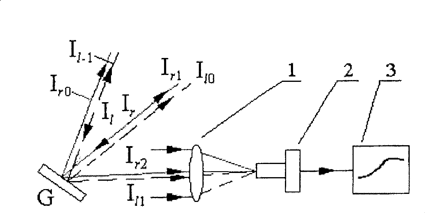
The monitoring device in this patent irradiates the recording light as the monitoring light on the latent image grating, and uses the photomultiplier tube to receive the diffracted light for real-time monitoring. Although the monitoring device does not need an external monitoring light source, the monitoring system becomes simple, but because The diffracted light energy of the latent image grating is very weak, and there is stray light from the recording light in the optical path. This part of the light energy is stronger than the diffracted light of the latent image grating and causes the background light to be too strong, so the actual operation is very inconvenient. The photomultiplier tube Receiving diffracted light from a latent image grating is very difficult

Method used


Image

  • Real-time monitoring device for light exposure in holographic grating production
  • Real-time monitoring device for light exposure in holographic grating production
  • Real-time monitoring device for light exposure in holographic grating production

Examples


Embodiment Construction

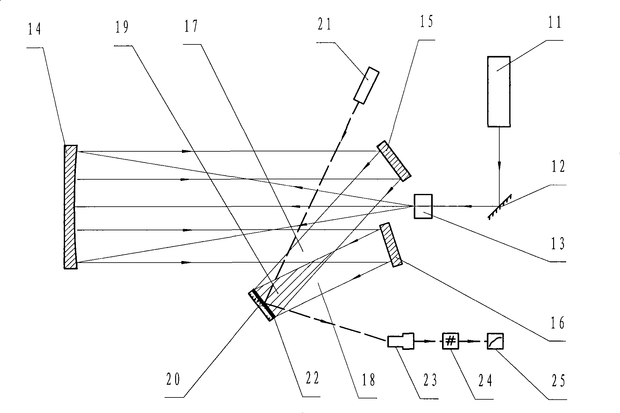
[0011] The invention presses figure 2 The technical solution shown is implemented, wherein the recording laser 11 uses a krypton ion laser with a wavelength of 413.1nm, the plane mirror 12 is a glass substrate aluminized mirror, and the spatial filter 13 is composed of a microscope objective lens and a pinhole, collimated and reflected The mirror 14 is made of K9 glass substrate with aluminized film, the diameter is ф320mm, the focal length f is 1200mm, the first adjustment mirror 15 and the second adjustment mirror 16 are glass substrate aluminized mirrors, the diameter is 160mm×110mm, the grating substrate is made 20 uses K9 optical glass. The photoresist coated on K9 optical glass is S1805 produced by Japan Shipley. The monitoring laser 21 uses a He-Ne laser with a wavelength of 632.8nm. The latent image grating 22 is made of photoresist. The photoelectric receiver 23 uses a photomultiplier tube, and the photomultiplier tube is only sensitive to the 632.8nm wavelength of the m...


PUM


Abstract

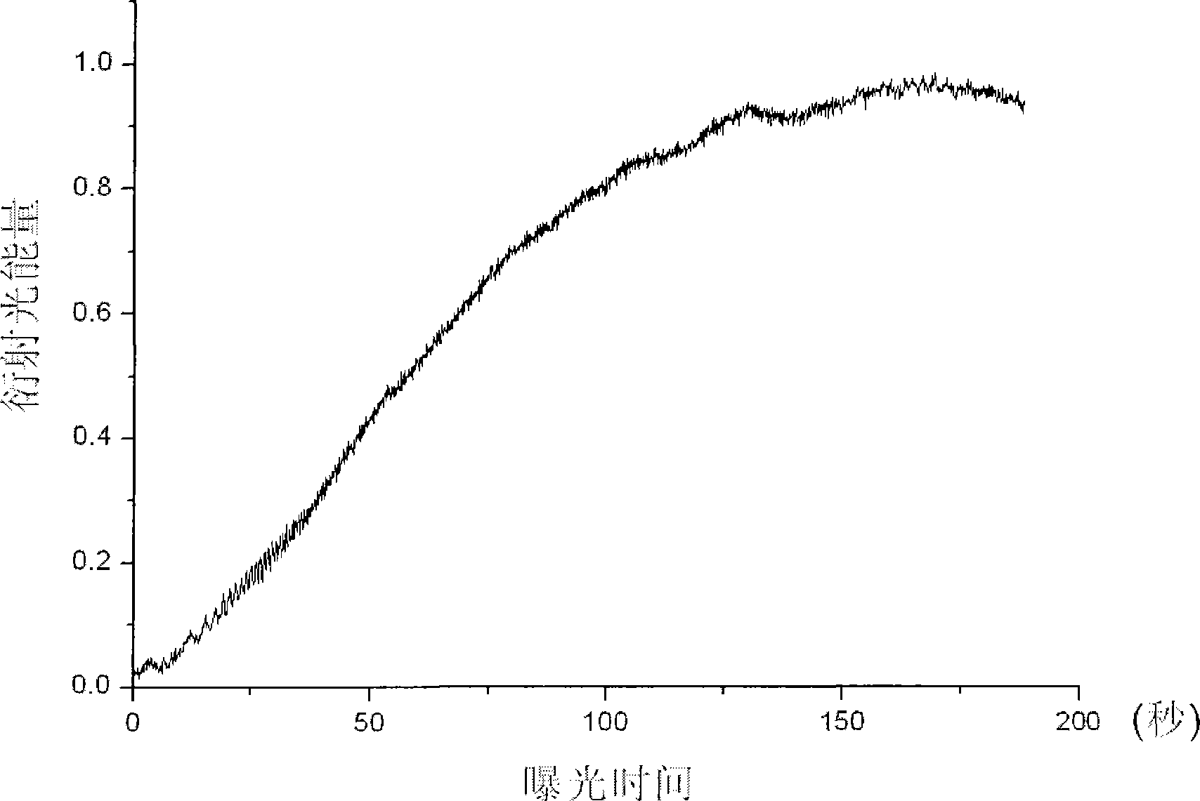
The invention discloses a real-time exposure monitoring device used in the manufacture of a holographic grating, belongs to the field of spectral technologies, relates to a real-time exposure monitoring device, and aims at solving the technical problem of providing the real-time exposure monitoring device used in the manufacture of the holographic grating. With regard to the technical proposal, the monitoring device comprises a grating substrate, a latent image grating, a recording beam, an interference field, a photoelectric receiver, a recording laser, a plane mirror, a spatial filter, a collimating mirror, a regulating mirror, a monitoring laser, a data processing system and a display. The grating substrate coated with a photoresist is placed in the interference field and exposed to form the latent image grating on the surface of the grating substrate, and the monitoring laser irradiates the latent image grating, the photoelectric receiver is arranged in the diffracted light direction, and the diffracted light is processed by the data processing system and then transmitted to the display, and the exposure can be obtained from the change of the diffracted light displayed on the display. The monitoring device can rapidly and automatically control the exposure of the holographic grating, accurately determine the exposure cut-off point, and provide a basis for the exposure technology of the holographic grating.

Description

Technical field [0001] The invention belongs to a real-time monitoring device for exposure in the production of holographic gratings in the field of spectroscopy technology. Background technique [0002] In the holographic grating manufacturing process, the amount of exposure is one of the important process parameters that need to be controlled, and neither under-exposure nor over-exposure can achieve an ideal grating groove shape. The traditional method is to use a fixed exposure time, through the production of a large number of samples, to repeatedly correct the exposure, sum up the best process parameters, and then use the experience value in the subsequent exposure. Due to the many process conditions that affect the quality of holographic gratings, this research method has a large experimental workload and a long period. In the end, good quality holographic gratings cannot be obtained. The existing technology closest to the present invention is that the Chinese patent number ...

Claims


Application Information

Patent Timeline
Patent Type & Authority Applications(China)
IPC IPC(8): G02B5/18G03F7/20G02B17/06G02B7/182
Inventor 李文昊巴音贺希格于宏柱王长庚孔鹏
Owner CHANGCHUN INST OF OPTICS FINE MECHANICS & PHYSICS CHINESE ACAD OF SCI
Learn More