Eureka AIR delivers breakthrough ideas for toughest innovation challenges, trusted by R&D personnel around the world.

Liquid-gas type vibration absorber

A liquid-gas shock absorber and shock absorber technology, applied in drilling equipment, earthwork drilling, drill pipe and other directions, can solve the problems of general shock absorption effect, small change range and small compressibility, and achieve shock absorption. Good effect, prevent secondary impact, increase the effect of applicability

Inactive Publication Date: 2009-05-13
中石化石油工程技术服务有限公司 +1
View PDF4 Cites 11 Cited by
  • Summary
  • Abstract
  • Description
  • Claims
  • Application Information

AI Technical Summary

Problems solved by technology

However, it is difficult to achieve the purpose of shock absorption by using the existing common shock absorbers, and there is an urgent need for a shock absorber with stronger applicability.
[0008] The various types of shock absorbers mentioned in the above literature have their own advantages, but they also have their own limitations. The hydraulic shock absorber has the characteristics of good stability, but the compressibility is small, the change range is small, and the shock absorber has its own advantages. The shock effect is general; the mechanical shock absorber has a wide application range and can be used for gas drilling, but the service life is short; the shock absorber that uses the volume change of gas with temperature and pressure changes has good flexibility, large change range, and good shock absorption effect. Good characteristics, but large impact, poor stability; therefore, there is an urgent need for a new type of shock absorber with good flexibility, wide application range, good stability and long service life. The present invention is proposed according to the above technical background

Method used


Image

  • Liquid-gas type vibration absorber
  • Liquid-gas type vibration absorber

Examples


Embodiment Construction

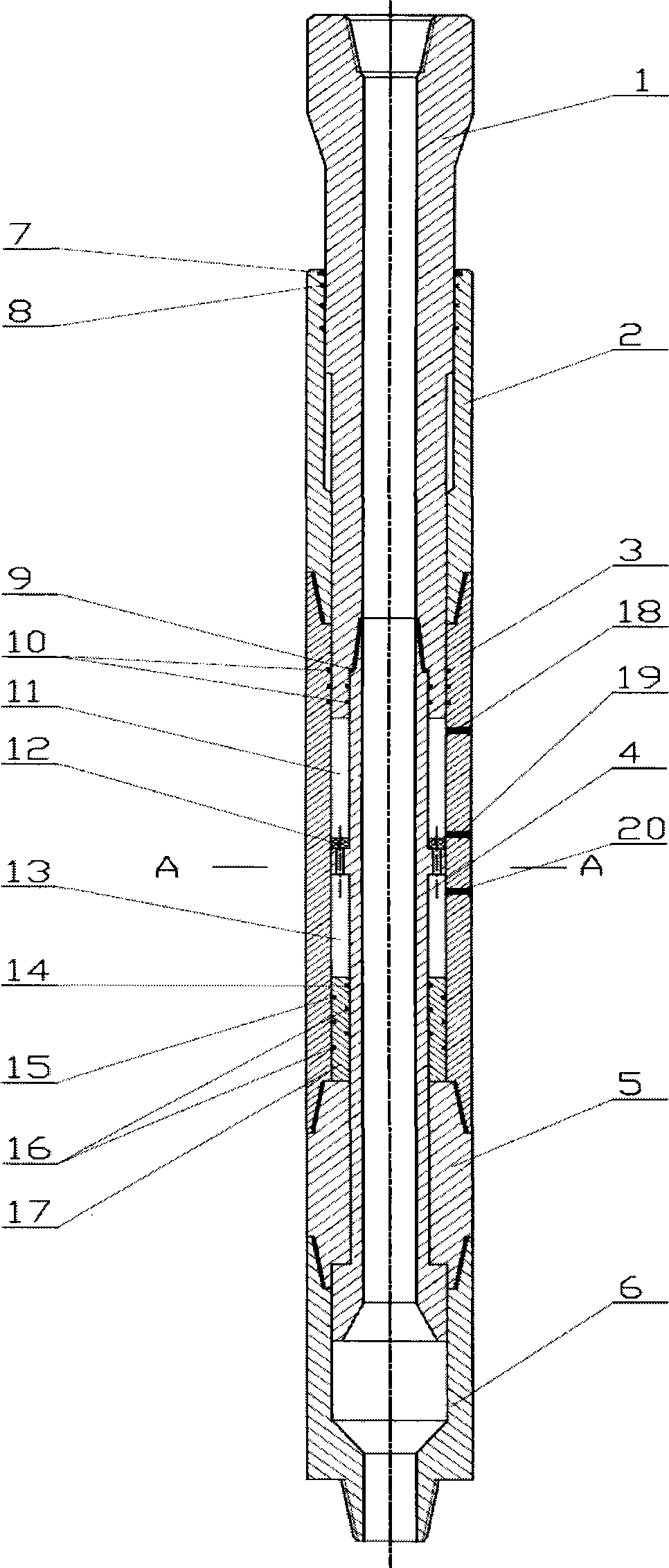
[0025] Combine now figure 1 , figure 2 Describe its invention further. According to the characteristic that the volume of gas changes with the change of temperature and pressure, the shock absorber uses gas as the elastic element, which has good shock absorption performance, and uses liquid as the pressure transmission element, which can not only increase the stability of the shock absorption system, Moreover, the gas is liquid-sealed, which increases the airtightness of the cylinder 11 .

[0026] The shock absorber presses figure 1 After assembly, according to the damping requirements, inject high-pressure gas into the cylinder through the gas nozzle 19, and inject low-pressure liquid into the liquid cylinder through the oil nozzle 20. And install it in the lower drilling tool assembly according to the need, and drill down to the bottom.

[0027] When impact and vibration loads occur on the drill bit, the lower joint 6 transmits the vibration load to the anti-drop joint ...


PUM


Abstract

The invention relates to a liquid gas type shock absorber, which consists of an upper connector, a spline external cylinder, a cylinder sleeve, a mandrel, a piston, a falling protection connector and a lower connector. The shock absorber is basically characterized in that the upper connector is connected with the spline external cylinder through a spline; the external cylinder of the shock absorber consists of the spline external cylinder and the cylinder sleeve; the mandrel and the piston are arranged inside the cylinder sleeve and are connected with the upper connector through thread; and the falling protection connector is connected with the cylinder sleeve and the lower connector through thread. According to the characteristic that the volume of gas changes along with the change of the temperature and pressure, the shock absorber adopts gas as an elastic element and has better shock absorbing performance. Simultaneously, liquid is taken as a pressure transfer element, thereby not only improving the stability of the shock absorbing system, but also carrying out the liquid sealing of the gas and consequently improving the tightness of the cylinder. The shock absorber has the advantages of wide application range, good flexibility, low impact, good stability, and the like.

Description

technical field [0001] The invention relates to a liquid-pneumatic shock absorber used in drilling engineering. Background technique [0002] This type of shock absorber in the prior art has the following patent documents to disclose. [0003] Chinese patent specification CN 85 2 02386 U (announcement on May 21, 1986) describes the hydraulic shock absorber for automatic drilling, the sum of the thrusts of each stage of the shock absorber under the pressure drop of the drill bit nozzle is Under the action of this thrust, the drilling pressure can realize the automatic feed on the piston stroke, and the piston-hydraulic cylinder at all levels is also a shock-absorbing element. [0004] Chinese patent specification ZL200520002102.3 (authorized on March 29, 2006) describes an air mechanical shock absorber suitable for underbalanced air circulation drilling, including a splined mandrel, a splined barrel, a disc spring barrel, a disc The shock absorber adopts the mechanical work...

Claims


Application Information

Patent Timeline
Patent Type & Authority Applications(China)
IPC IPC(8): E21B17/07
Inventor 赵金海唐波闫振来王敏生史洪军
Owner 中石化石油工程技术服务有限公司
Why Eureka
Eureka Blog
Learn More