
Corroson-resistant steel material for crude oil storage tank, and crude oil storage tank

A crude oil tank and steel technology, which is applied in the field of crude oil tanks and corrosion-resistant steel, can solve the problems of large construction and inspection costs, coating film damage and corrosion, and achieve excellent general corrosion resistance and local corrosion resistance.

Active Publication Date: 2009-04-22
JFE STEEL CORP
View PDF2 Cites 16 Cited by
  • Summary
  • Abstract
  • Description
  • Claims
  • Application Information

AI Technical Summary

Problems solved by technology

However, it has been pointed out that since crude oil tanks have a large coating area and need to be recoated every 10 years, coating crude oil tanks will cost a lot of construction and inspection costs. In addition, in the environment of crude oil tanks However, the application of a thick coating promotes the corrosion of the damaged part of the coating film.

Method used


Image

  • Corroson-resistant steel material for crude oil storage tank, and crude oil storage tank
  • Corroson-resistant steel material for crude oil storage tank, and crude oil storage tank
  • Corroson-resistant steel material for crude oil storage tank, and crude oil storage tank

Examples


Embodiment 1

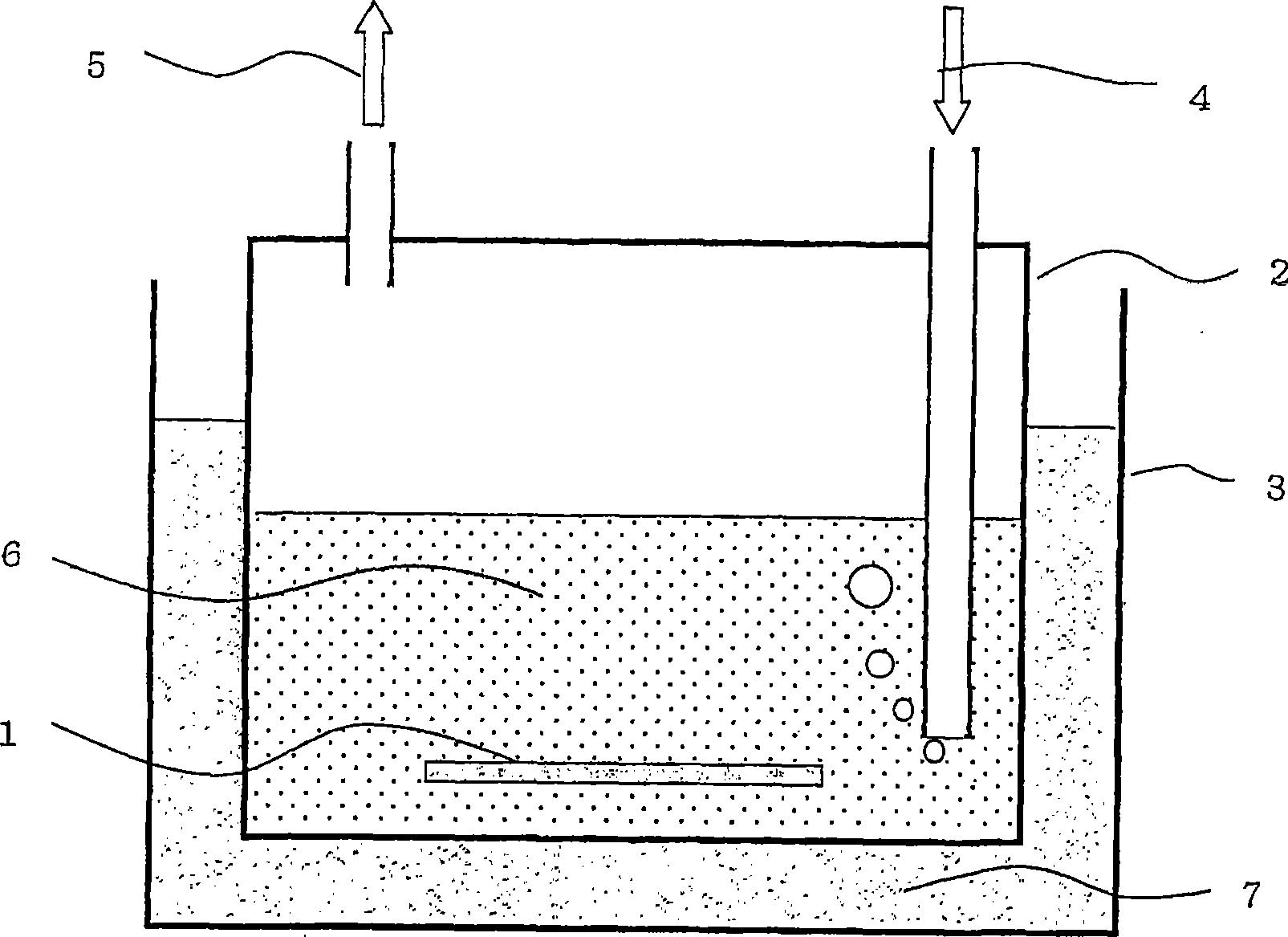
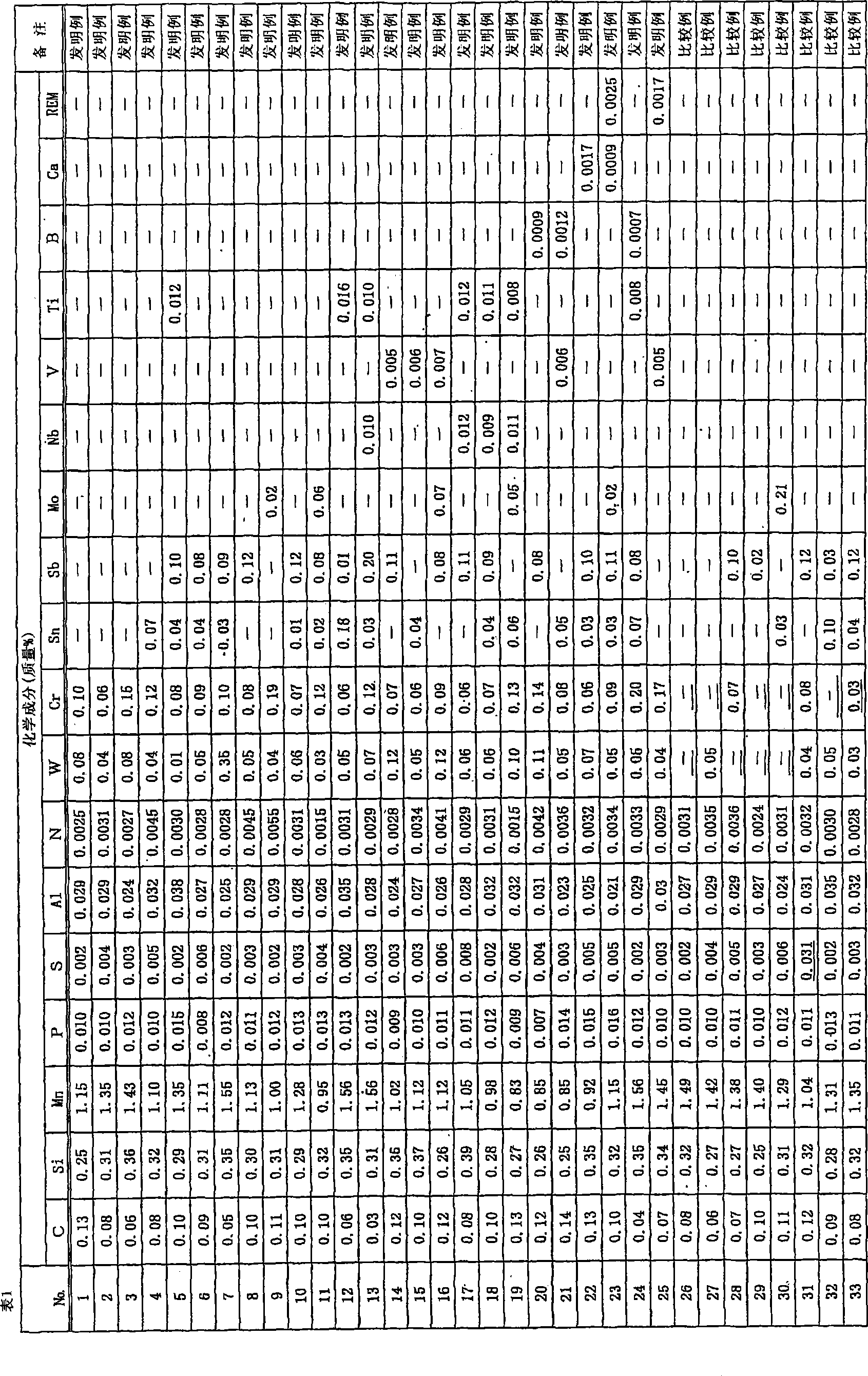
[0088] Steels having various compositions of Nos. 1 to 33 shown in Table 1 are melted in a vacuum melting furnace or a converter, and these steel slabs are reheated to 1200°C, and hot-rolled at 800°C as the final rolling finish temperature , to make a thick steel plate with a thickness of 16mm.

[0089] From the steel plates No.1 to 33 obtained in this way, cut out a square piece with a width of 50 mm x a length of 50 mm x a thickness of 15 mm. ~10μm, 15~25μm, 50~70μm four kinds of inorganic zinc primer thickness, make the test piece. Then, while covering the end surface and inner surface of the test piece with anticorrosive paint, only on the upper surface of the test surface is uniformly coated with oil sludge containing crude oil components taken from the actual oil tank to form a corrosion resistance test piece. test piece. Here, two types of corrosion test pieces having different surface states were produced. That is, a test piece (test 1) in which oil sludge was unifo...

Embodiment 2

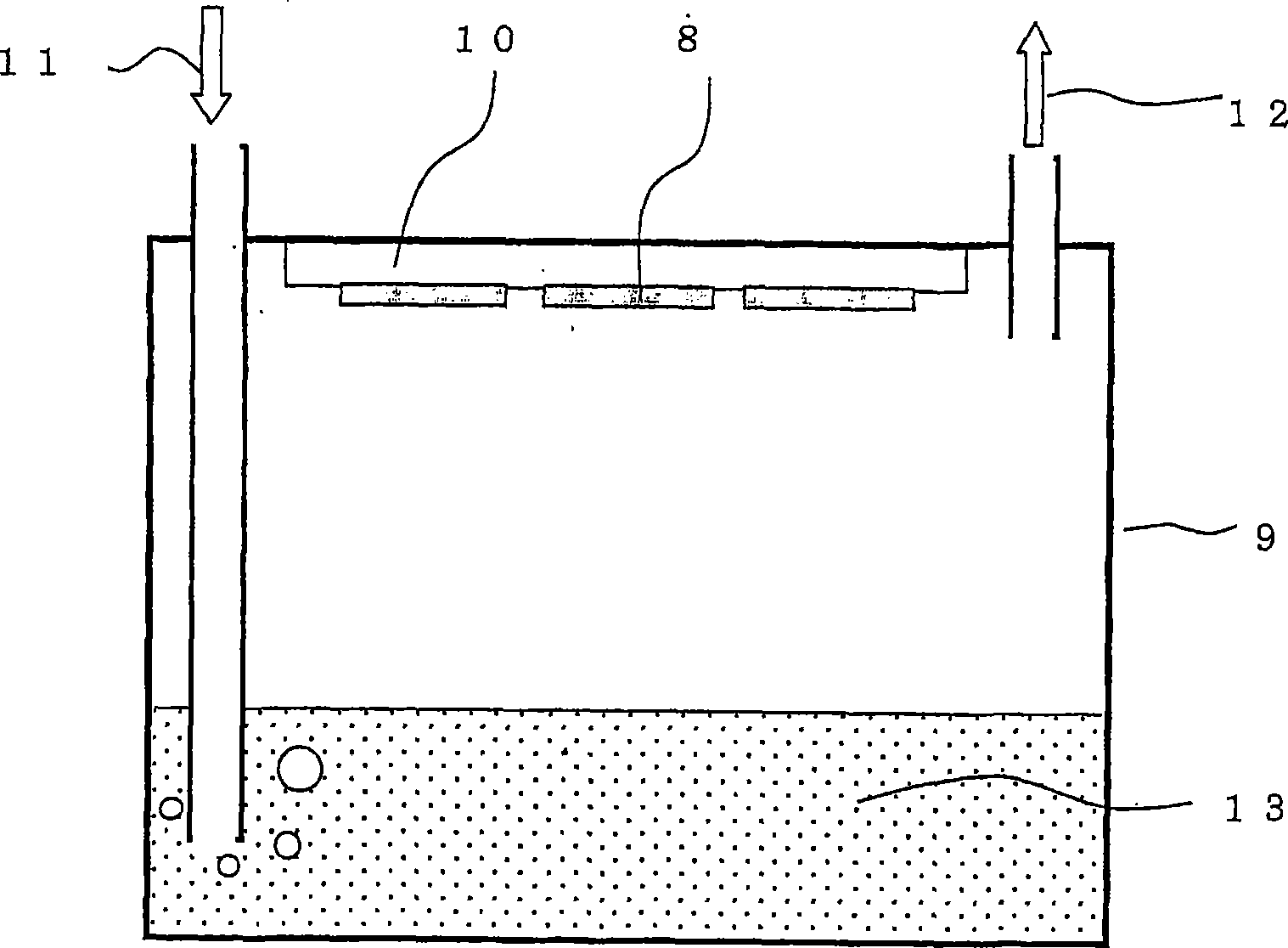
[0104] From the same No.1~33 steel plates that are used in Example 1, cut out the rectangular small piece of wide 25mm * length 48mm * thick 4mm, after its surface is carried out sandblasting, coating film thickness is 0 μ m ( No coating), 5 ~ 10μm, 15 ~ 25μm, 50 ~ 70μm four kinds of inorganic zinc primers, made of test pieces, and then, in order to accelerate the corrosion resistance test, on the surface of the above coating film, formed to reach the steel The X-shaped cuts on the surface were used to make the damage area ratio 1.0%, and a corrosion test piece was made.

[0105] For these test pieces, use figure 2 The corrosion test apparatus shown in the figure is a general corrosion test that is likely to occur in the environment inside the upper deck of a crude oil tank. The corrosion test device is composed of a corrosion test tank 9 and a temperature control plate 10, and water 13 is injected into the corrosion test tank 9, and the temperature is maintained at 40°C. I...


PUM


Abstract

Disclosed is a steel material which, when used in an oil tank for an oil tanker, a tank for transporting a crude oil, a tank for storage of a crude oil or the like, can reduce a local corrosion on a bottom plate or a general corrosion on a top board or a side board. The steel material for a crude oil storage tank has the following chemical composition: C: 0.001-0.16 mass%, Si: 0.01-1.5 mass%; Mn: 0.1-2.5 mass%; P: 0.025 mass% or less; S: 0.01 mass% or less; Al: 0.005-0.1 mass%; N: 0.001-0.008 mass%; W: 0.001-0.5 mass%; and Cr: not less than 0.06 mass% and less than 0.20 mass%; with the remainder being Fe and unavoidable impurities.

Description

technical field [0001] The present invention relates to a corrosion-resistant steel material capable of reducing localized corrosion at the bottom plate and general corrosion at the deck or side plate when the steel material for crude oil tanks is used in a bare state or in a primed state, and the resulting Crude oil tanks made of steel. The crude oil tank mentioned in the present invention is a general term for oil tanks of oil tankers, oil tanks for transporting crude oil, and oil tanks for storing crude oil, etc. . Background technique [0002] Known: inert gas (in O) filled in crude oil tanks for explosion protection 2 : 5% by volume, CO 2 : 13% by volume, SO 2 : 0.01% by volume, the balance being N 2 O 2 , CO 2 , SO 2 , or H volatilized from crude oil 2 Corrosive gases such as S will cause general corrosion on the upper inner surface of the crude oil tank of the tanker (the inner surface of the upper deck). [0003] Moreover, the H 2 S is oxidized by the cata...

Claims


Application Information

Patent Timeline
IPC IPC(8): C22C38/00
CPCC22C38/06C22C38/02C22C38/04C22C38/60C22C38/22
Inventor 盐谷和彦猪原康人小森务
Owner JFE STEEL CORP
Learn More