Coating with carbon nitride and carbon nitride coated product
A carbonitride and product technology, applied in coating, sputtering, vacuum evaporation coating, etc., can solve the problems of unstable operation, slow plasma productivity, narrow scanning width, etc. The effect of small chamber volume and increased coating productivity
- Summary
- Abstract
- Description
- Claims
- Application Information
AI Technical Summary
Problems solved by technology
Method used
Image

Examples
preparation example Construction
[0090] The invention further enables the production of three-dimensional structures, wherein parts of the product are used as scaffolds for growing said three-dimensional structures.
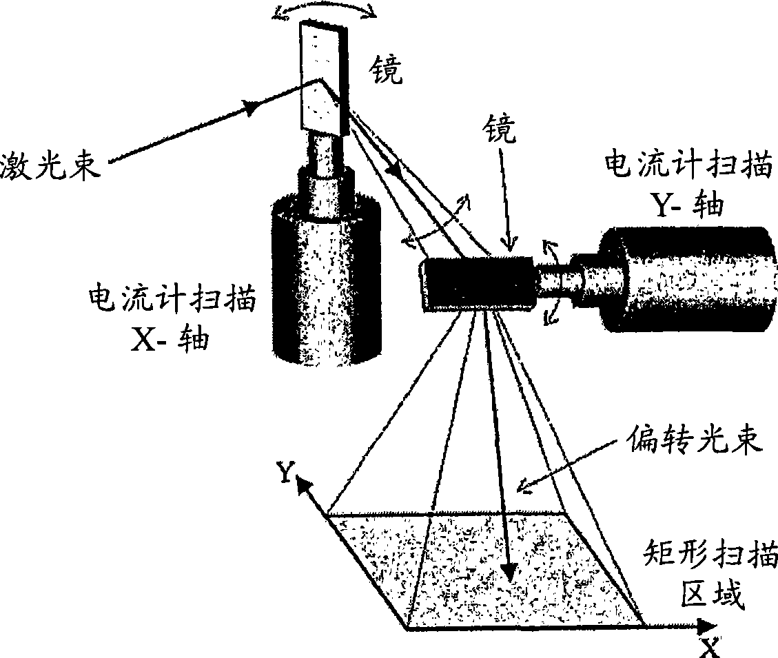
[0091] According to the invention there is also provided a carbonitride-coated product comprising a defined surface coated by laser ablation, wherein the coated uniform surface area comprises at least 0.2 dm 2 And the coating has been done by using ultrashort pulse laser deposition, wherein the pulsed laser beam is scanned with a rotating optical scanner comprising at least one mirror for reflecting said laser beam. The benefits obtained from these products are described in more detail in the previous method description.
[0092] In a preferred embodiment of the invention, said uniform surface area comprises at least 0.5 dm 2 . In a more preferred embodiment of the invention, said uniform surface area comprises at least 1.0 dm 2 . The present invention also easily realizes the 2 (such as 1m...
example
[0102] Example used to illustrate known technical issues - laser technology
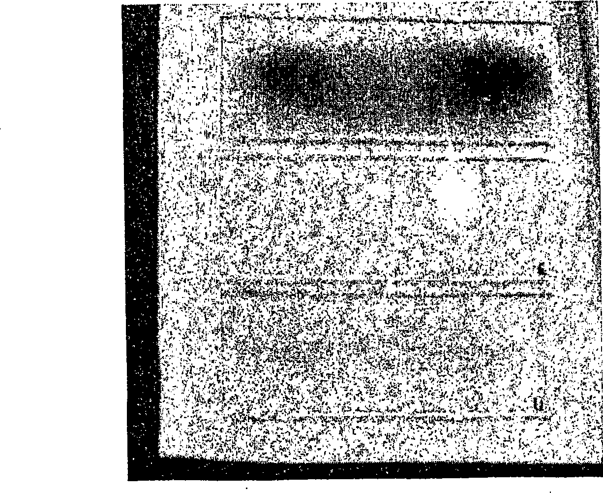
[0103] figure 2 represents ITO of different ITO film thicknesses (30 nm, 60 nm, and 90 nm) fabricated on polycarbonate plates (~100 mm × 30 mm) by employing a state-of-the-art optical scanner (i.e., vibrating mirror (galvano scanner)). coating. Although this ITO coating was not deposited on a metal substrate, the figure clearly shows the similarity with the use of vibrating mirrors as optical scanners (usually used especially in ultrashort pulse laser deposition (USPLD) and in laser-assisted coating middle) related issues. When the oscillating mirror changes its direction of angular motion at its end positions, and due to the moment of inertia (moment of inertia), the angular velocity of the mirror is not constant near its end positions. Due to the oscillating motion, the mirror is continuously braked and stopped before being accelerated again, thus causing irregular handling of the target materi...
example -1
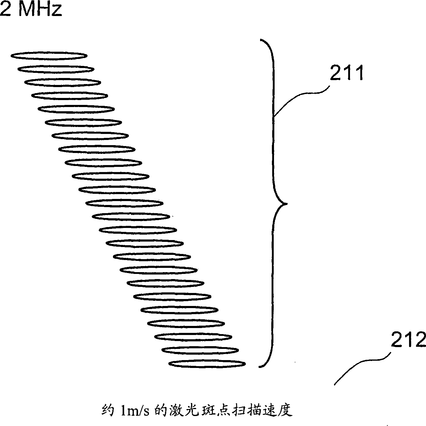
[0111] Figure 13a shows a target material ablated with a pulsed laser in the picosecond range using a rotary scanner at a velocity that achieves ablation of the target material with adjacent pulses slightly overlapping, avoiding the hurdles of the prior art. Electron scanner related issues. Figure 13b shows a magnified view of a portion of the ablated material, clearly showing the smooth and controlled ablation of material along both the x- and y-axes, and thus the generation of high-quality, particle-free plasma body and further produces high-quality films and coatings. Figure 13c shows an example of a single ablation site possible in x- and y-dimensions achieved by one or a few pulses. Here, it can be clearly seen that the invention achieves ablation of material in such a way that the width of the ablation point is always greater than the depth of the area of the ablation point. Theoretically, possible particles (if they would be generated at all) could now have the maxi...
PUM
| Property | Measurement | Unit |
|---|---|---|
| surface roughness | aaaaa | aaaaa |
| thickness | aaaaa | aaaaa |
| diameter | aaaaa | aaaaa |
Abstract
Description
Claims
Application Information
 - Generate Ideas
- Intellectual Property
- Life Sciences
- Materials
- Tech Scout
- Unparalleled Data Quality
- Higher Quality Content
- 60% Fewer Hallucinations
Browse by: Latest US Patents, China's latest patents, Technical Efficacy Thesaurus, Application Domain, Technology Topic, Popular Technical Reports.
© 2025 PatSnap. All rights reserved.Legal|Privacy policy|Modern Slavery Act Transparency Statement|Sitemap|About US| Contact US: help@patsnap.com