Undersea optical transmission system employing low power consumption optical amplifiers

An optical amplifier and optical transmission technology, applied in the field of optical transmission systems, can solve the problems of high capital investment, large inventory equipment purchase costs, long-range technology that cannot economically reduce small length and capacity requirements, etc.

Inactive Publication Date: 2009-01-28
HUAWEI MARINE NETWORKS CO LTD
View PDF5 Cites 8 Cited by
  • Summary
  • Abstract
  • Description
  • Claims
  • Application Information

AI Technical Summary

Problems solved by technology

Although the technology used is very capable, it is complex and time consuming to design, test and deploy
Although the cost per bit delivered is often attractive if the system is scaled up to the maximum design capacity by Dense Wavelength Division Multiplexing (DWDM) technology, where many data streams with varying wavelengths are simultaneously carried on the same line, long-haul The initial capital cost in the system tends to be very high
[0008] Long-range technologies generally cannot be economically scaled down to systems with smaller length and capacity needs
Since the bandwidth requirements on shorter regional routes are less compared to large transoceanic "pipes", high design capacity cannot be achieved in order to achieve the favorable economics associated with long-haul technology
also, since long-haul technology is purposely designed to meet the long-distance and high-bandwidth capacity required in the region, it is not possible to make long-haul platforms suitable for regional markets simply from a characterization and engineering standpoint
[0009] For any new business attempting to enter any of these markets, there are considerable barriers to entry, including but not limited to, high capital investment, long time to market, and large inventory Technology that may be obsolete in time cycle

Method used


Image

  • Undersea optical transmission system employing low power consumption optical amplifiers
  • Undersea optical transmission system employing low power consumption optical amplifiers

Examples


Embodiment Construction

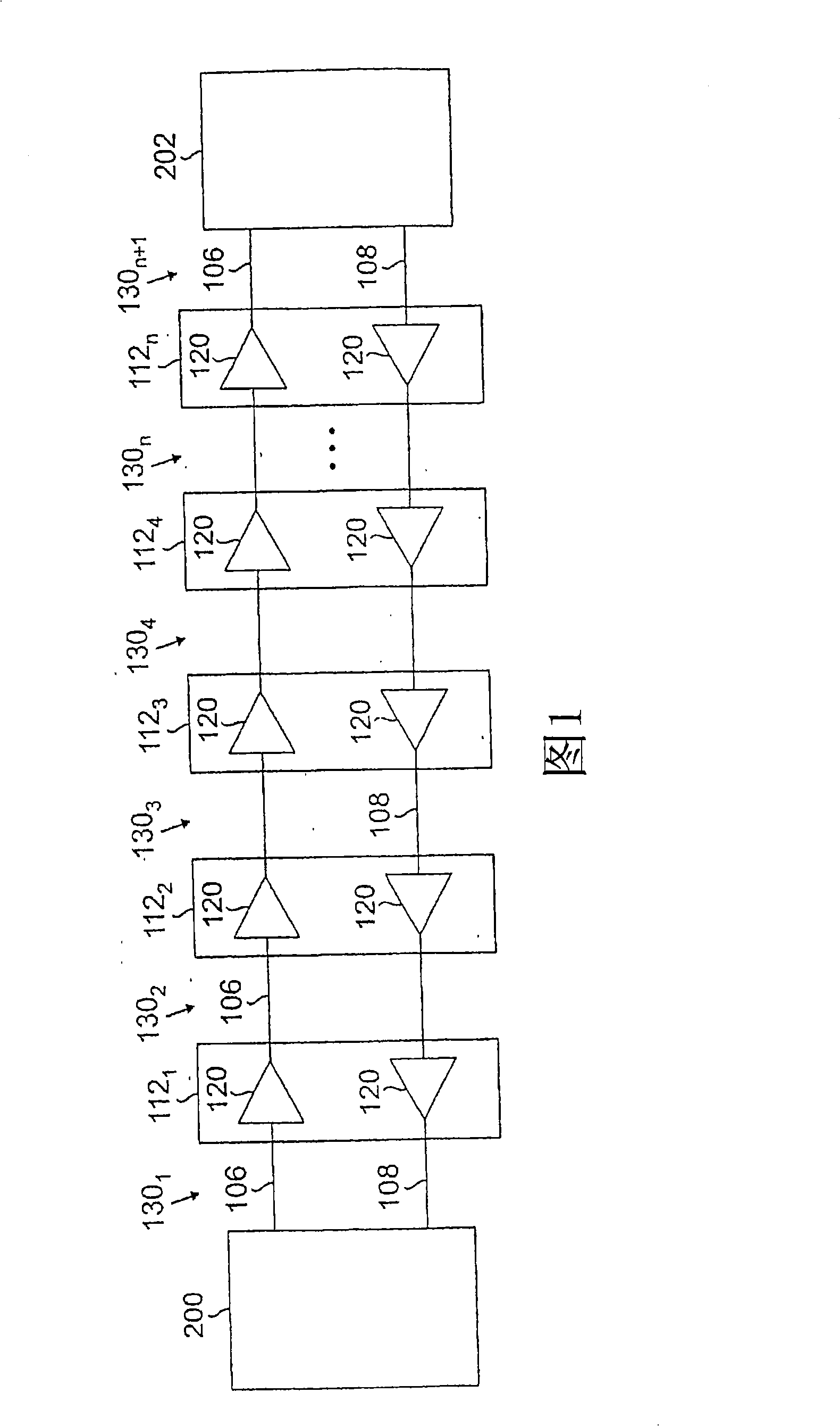
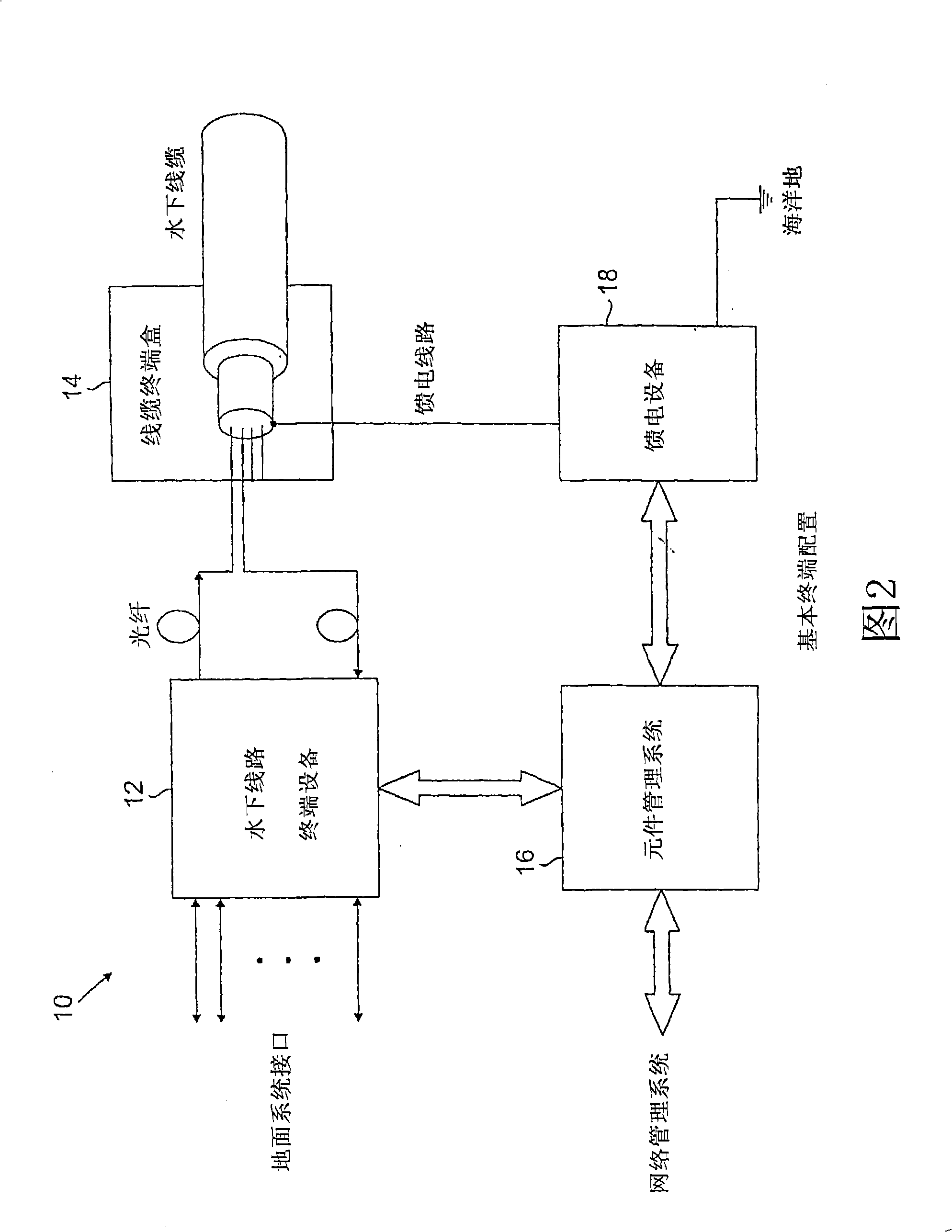
[0022] Figure 1 shows an exemplary wavelength division multiplexing (WDM) transmission system in which the present invention may be used. The transmission system is used to transmit multiple optical channels over unidirectional fiber pairs 106 and 108 between cable stations 200 and 202 . Optical fibers 106 and 108 are housed in fiber optic cables, which also include power conductors for providing power to the repeaters. Cable stations 200 and 202 are of the type shown in FIG. 2 . The transmission path is divided into transmission spans or links 130 1 、130 2 、130 3 、...130 n+1 . transmission span 130 by repeater 112 1 、112 2 、...112 n connected and range in length from 40 to 120 km, or possibly even longer if Raman amplification is used. The repeater includes an optical amplifier 120 connecting each span 130 . It should be noted that the invention is not limited to point-to-point network architectures such as that shown in Figure 1, but more generally can cover more c...


PUM


Abstract

An undersea WDM optical transmission system is provided. The system includes first and second land-based cable stations, at least one of the cable stations includes power feed equipment (PFE) supplying electrical power to the cable at a voltage of no more than about 6 kv or less. The PFE is located in at least one of the cable stations. The system also includes an undersea WDM optical transmission cable having a length corresponding to those required in the undersea regional market. The cable includes at least one optical fiber pair for supporting bidirectional communication between the first and second cable stations. At least one repeater is located along the optical transmission cable. The repeater includes at least two optical amplifiers each providing optical gain to one of the optical fibers in the optical fiber pairs. The optical gain is in a range from about 12 to 20 dB.

Description

[0001] Related Application Instructions [0002] This application claims priority to U.S. Provisional Patent Application Serial No. 60 / 557,343, filed March 29, 2004, entitled "Method For Commoditizing Elements of Previously Specialized Communications Link," the entire contents of which, including the drawings, are incorporated herein by reference to Enter as a reference. [0003] This application is related to U.S. Patent Application Serial No. 10 / 870,327, filed June 17, 2004, entitled "Submarine optical Transmission Systems Having Optical Amplifiers Of Unitary Design," and filed December 18, 2003, entitled "Method For Commoditizing Elements of Previously Specialized Communications Links," U.S. Patent Application Serial No. 10 / 739,929, the entire contents of which, including the drawings, are hereby incorporated by reference. technical field [0004] The present invention relates generally to optical transmission systems, and more particularly, to subsea optical transmission ...

Claims


Application Information

Patent Timeline
Patent Type & Authority Applications(China)
IPC IPC(8): H04B10/00H04B10/297H04B10/80
Inventor 史蒂芬·G·小埃旺热利迪斯迈克尔·J·纽贝尔特杰伊·P·莫雷亚莱马克·K·扬乔纳森·A·纳格尔大卫·S·德温森蒂斯
Owner HUAWEI MARINE NETWORKS CO LTD
Why Eureka
Try Eureka