
Aluminum alloy non-welding and roof tile solar heat collector

A solar heat collector and welding-free technology, which is applied in the field of solar heat collectors, can solve the problems that the structure and function of solar heat collectors cannot be properly combined, the speed of popularization of heat collectors is slow, and it is not suitable for large-scale use. Reduce heat transfer distance, improve heat collection efficiency, and reduce material cost

Inactive Publication Date: 2009-01-28
范东杰
View PDF0 Cites 14 Cited by
  • Summary
  • Abstract
  • Description
  • Claims
  • Application Information

AI Technical Summary

Problems solved by technology

The main problems are: first, there is no high-efficiency and low-cost collector, which leads to slow promotion; second, the maintenance is difficult due to the low reliability of process materials; third, the structural function of the solar collector and the structural function of the building cannot be properly to combine
The production cost of all kinds of glass vacuum tube solar collectors is high, and the use of close arrangement will double the cost and make the processing difficult. The effect is greatly affected and frequent maintenance is required. Compared with traditional flat-plate solar collectors, it is not suitable for large-scale use

Method used


Image

  • Aluminum alloy non-welding and roof tile solar heat collector
  • Aluminum alloy non-welding and roof tile solar heat collector
  • Aluminum alloy non-welding and roof tile solar heat collector

Examples


Embodiment Construction

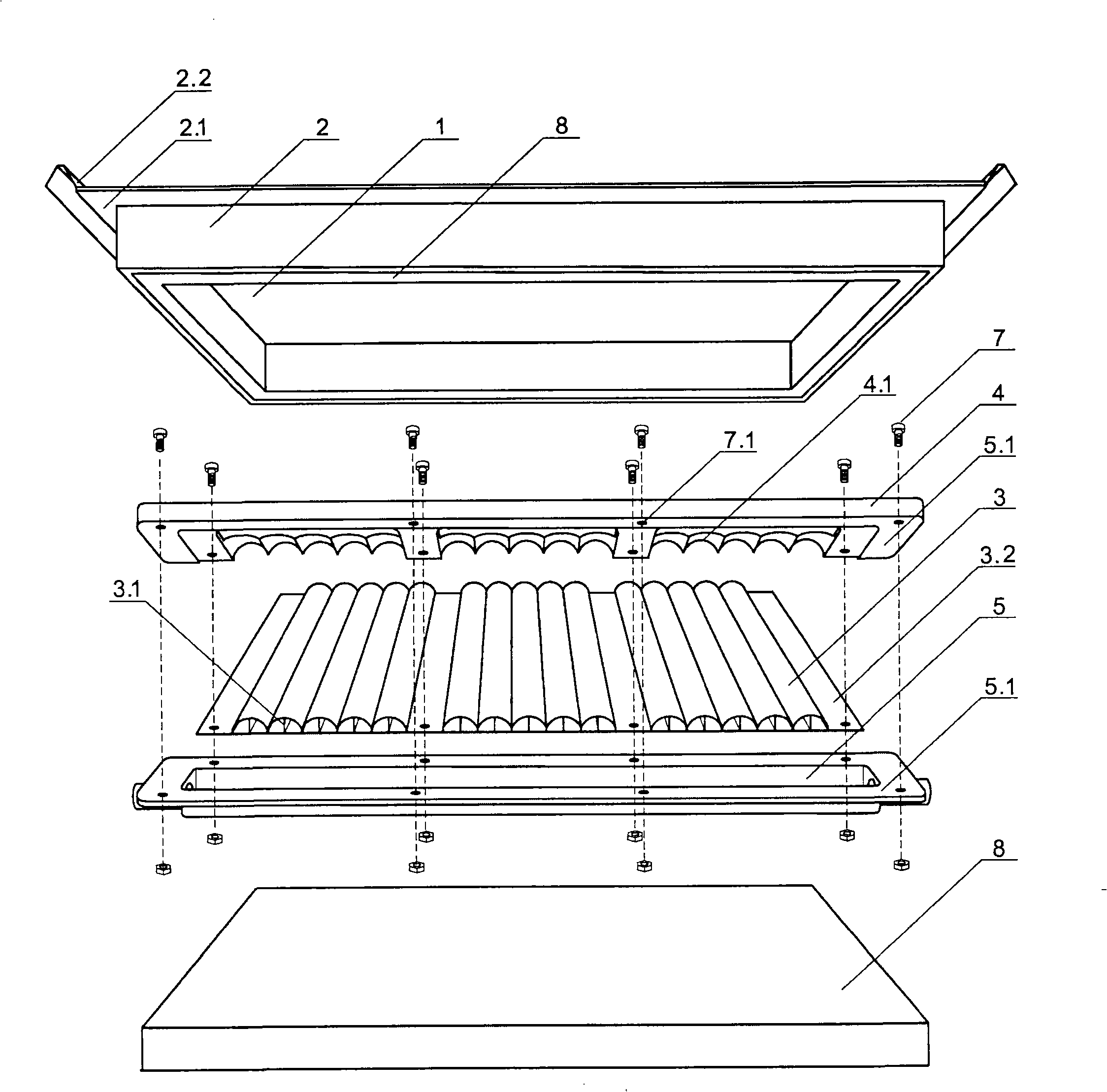
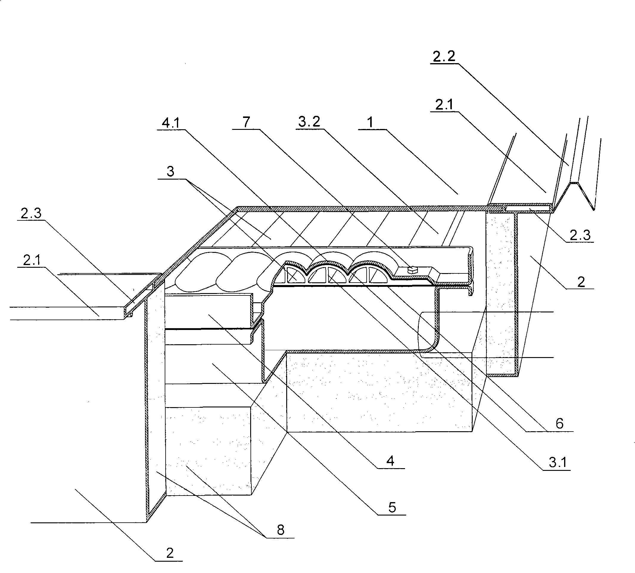
[0043] Examples see figure 1 , 2 As shown, this aluminum alloy solar collector mainly includes a glass cover plate 1, a frame 2, a water pipeline cover plate 4, a heat collecting plate and a heat exchange container 3, and a water pipeline tank 5 arranged and assembled in sequence from the light receiving surface. and insulation layer 8.

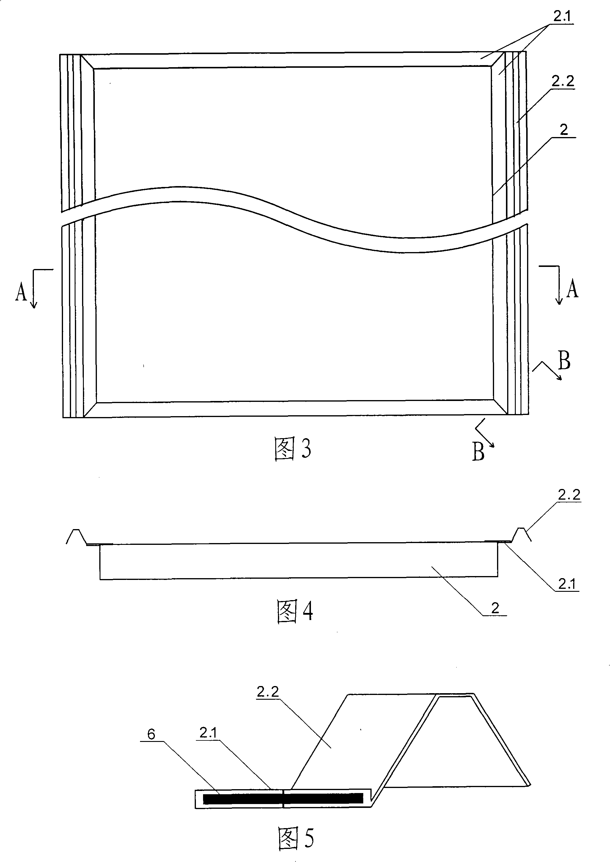
[0044] see Figure 1-6 , the glass cover plate 1 is a heat-resistant light-transmitting glass plate, which is used to allow sunlight to fully pass through and reduce heat loss; it can withstand long-term cold, heat, light, wind, rain, and snow erosion during use, and is subject to hail , stones and other external force collisions will not be damaged. The effect of insulation layer 8 is to reduce heat collector to radiate heat to surrounding environment, require material thermal conductivity to be little, do not absorb water etc., preferably use polyurethane foam product, mineral wool product or expanded polystyrene board. The function of ...


PUM

PropertyMeasurementUnit
tensile strengthaaaaaaaaaa
shear strengthaaaaaaaaaa

Abstract

The invention discloses an aluminum alloy welding-free and roofing-tile solar collector, wherein, a collecting board is integrated with a heat-exchanging container; the solar collector is a section material with a semi-circle and tubular-shaped transect, the upper part of which is cambered and the lower part of which is flat, and connected with a plurality of aluminum alloy pipes which are connected with each other in parallel; the sunny side of the solar collector is coated with a selective heat absorption coating; water pipes which are arranged at the two sides of the solar collector and connected with the pipe section material are metal water pipes that are divided into an upper part and a lower part and has a pipe section material interface; the pipe section material and the water pipe are connected firmly by bolts and sealed by a sealant, and the upper part and the lower part of the water pipe are connected firmly by the bolts and sealed by the sealant; a glass cover plate is arranged on the pipe section material and the water pipe; a thermal insulation layer is arranged below the pipe section material and the water pipe; borders enclose the solar collector into a sealed whole at the periphery and extend out of regulas in all directions on the plane of the glass cover plate; the regulas on the left and right rise upwards so that the solar collection has the function of a large insulation roofing tile. The solar collector has the advantages of high heat collection efficiency, low price and long service life, basically requiring no maintenance, and being integrated with buildings and beneficial to scale production.

Description

(1) Technical field [0001] The invention relates to a solar heat collector (2) Background technology [0002] Solar energy utilization is the development direction of energy-saving buildings. Traditional solar collectors mainly include flat plate collectors and vacuum collectors. The main problems are: first, there is no high-efficiency and low-cost collector, which leads to slow promotion; second, the maintenance is difficult due to the low reliability of process materials; third, the structural function of the solar collector and the structural function of the building cannot be properly combined. [0003] In order to improve the heat transfer speed, the traditional flat-plate solar collector uses more copper materials. The manufacturing process adopts brazing, resistance welding, ultrasonic welding, high-frequency welding, copper-aluminum composite, etc., and requires metal phase combination to reduce heat loss. resistance. The advantage of this kind of flat-plate sol...

Claims


Application Information

Patent Timeline
Patent Type & Authority Applications(China)
IPC IPC(8): E04D13/18F24J2/00F24J2/04F24J2/46F24J2/48F24J2/51
CPCY02B10/20Y02E10/44F24J2/0455F24S20/69Y02E10/40
Inventor 范东杰
Owner 范东杰
Learn More