
Device and method for cleaning exhaust air of engine

An exhaust gas cleaning and engine technology, which is applied to exhaust devices, engine components, machines/engines, etc., can solve problems such as inability to replace, fail to function, and increase engine fuel consumption, and achieve the effect of solving pollution problems.

Inactive Publication Date: 2009-01-21
曾肇贤 +1
View PDF2 Cites 6 Cited by
  • Summary
  • Abstract
  • Description
  • Claims
  • Application Information

AI Technical Summary

Problems solved by technology

The disadvantage is that if water enters the engine combustion chamber, the engine will be damaged; and the engine exhaust gas is a high-temperature gas, spraying water in the exhaust gas pipe will cause thermal expansion and contraction, and the metal is prone to fatigue and oxidation, greatly shortening the service life
Additionally, if the water is lost, used up, or damaged, the vehicle exhaust is released into the air completely untreated
[0005] In the Chinese utility model patent with the authorized notification number CN 2324291Y, a motor vehicle harmless exhaust exhaust muffler is disclosed. Although it can achieve the purpose of environmental protection to a certain extent, it needs to make the exhaust gas pass through the water, so that the fuel consumption of the engine is reduced. volume increase
In addition, if the water consumption is too high and the water level is lower than the exhaust pipe opening, the device will lose its normal function and will not work
Drivers need to add and change water regularly in a short period of time. If the pollutants accumulate too much, the honeycomb filter will fail and cannot be replaced, leaving waste water inside the device that cannot be processed.

Method used


Image

  • Device and method for cleaning exhaust air of engine
  • Device and method for cleaning exhaust air of engine

Examples


Embodiment Construction

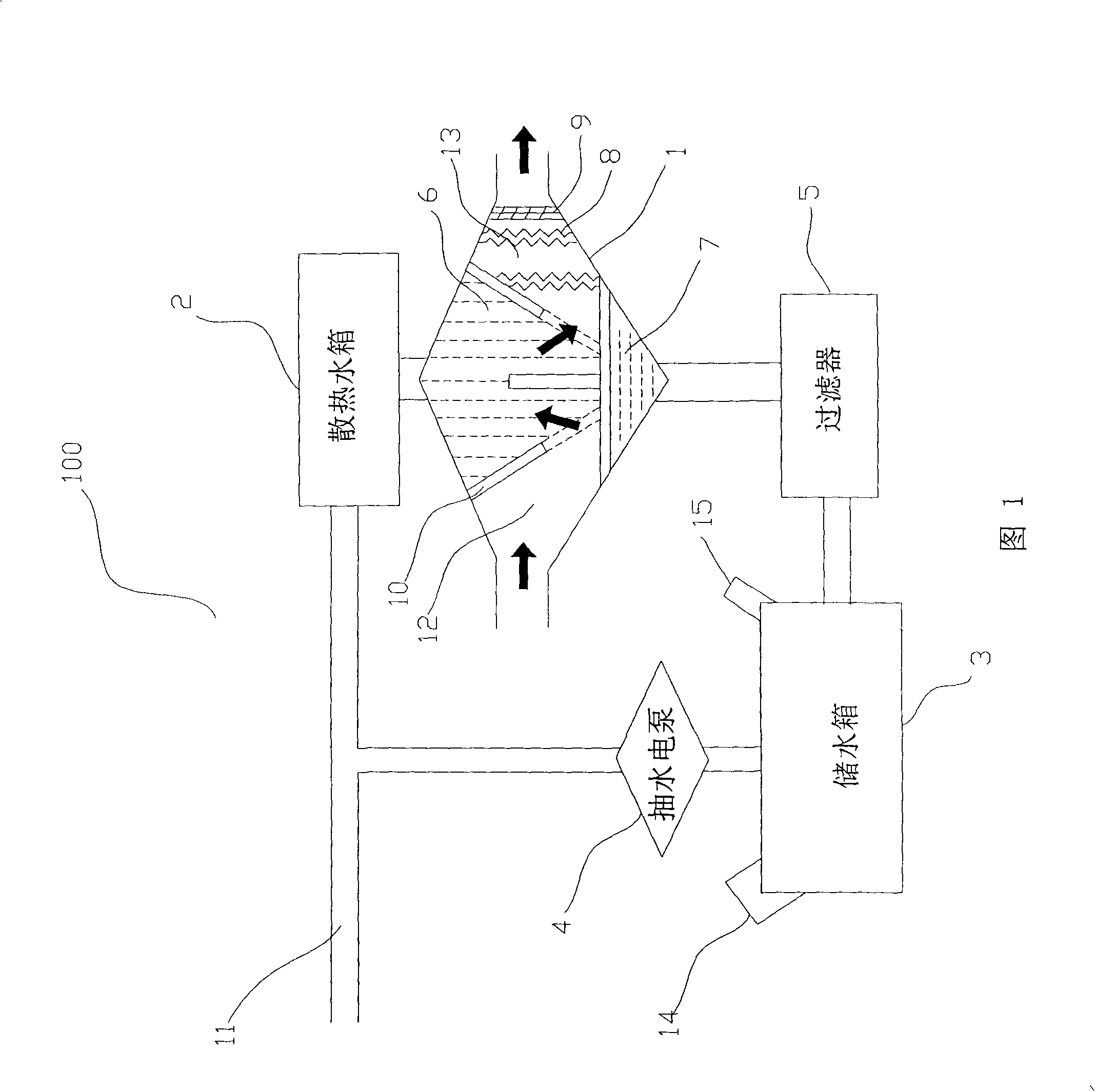
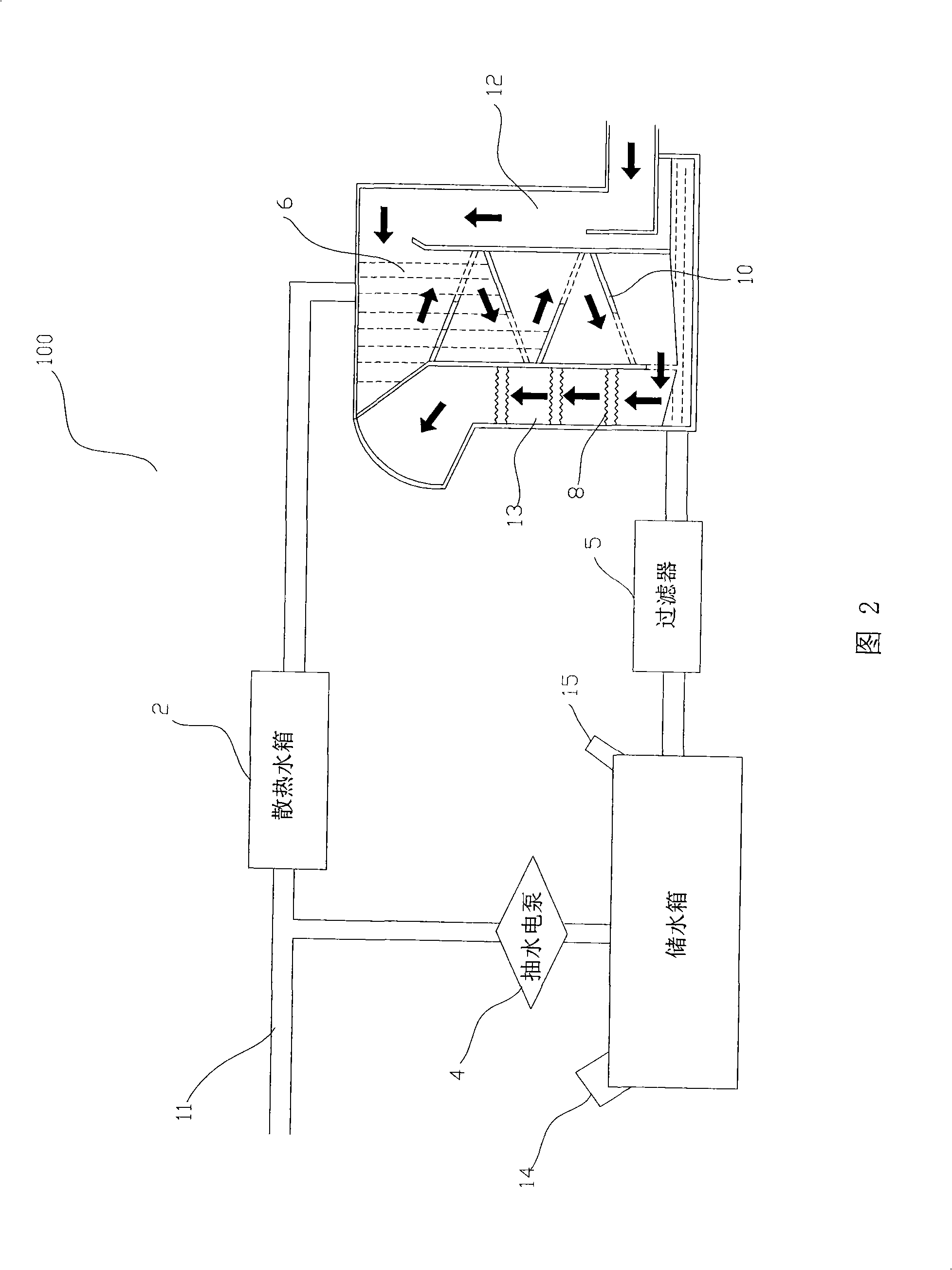
[0030] As shown in Figure 1, the first embodiment of the present invention is suitable for small vehicles, wherein the engine exhaust gas cleaning device 100 includes a cleaning exhaust gas drum 1, a cooling water tank 2 connected to the cleaning exhaust gas drum 1 top, and a filter 5 with the cleaning exhaust gas The water storage tank 3 connected below the drum 1. The inlet of the cleaning exhaust drum 1 is connected with the outlet of the exhaust pipe of the vehicle, so that the exhaust gas produced by the engine enters; its outlet is used to discharge the exhaust gas. The water storage tank 3 is connected to the heat dissipation water tank 2 through the pumping electric pump 4, and the working voltage of the pumping electric pump 4 is 12V-24V, which is used to pump the water in the water storage tank 3 into the heat dissipation water tank 2, and enter the cleaning exhaust gas drum after heat dissipation and cooling 1. The cleaning waste gas drum 1 is connected with the fi...


PUM


Abstract

The invention relates to an engine exhaust gas cleaning device and a method; the device is used for cleaning the exhaust gas discharged by vehicles and includes an exhaust gas cleaning drum, a heat dissipating water tank which is connected above the exhaust gas cleaning drum and a storage water tank which is connected under the exhaust gas cleaning drum by a filter; the storage water tank is connected with the heat dissipating water tank through an electric water pump; the exhaust gas cleaning drum is provided with an inlet which is connected with an exhaust gas discharge pipe of a vehicle and an outlet which is used for discharging; a buffer zone used for slowing the flow speed of exhaust gas and a buffer spaying zone used for cleaning exhaust gas are sequentially arranged between the inlet and the outlet. The device can be matched with the existing exhaust treatment device on vehicles for use and can assist to further solve the pollution problem of vehicle emissions, while vehicles do not need to be remodeled.

Description

technical field [0001] The invention relates to the field of exhaust gas treatment, and more specifically relates to an engine exhaust gas cleaning method and device. Background technique [0002] The invention of the automobile has brought great convenience to human life, but the exhaust gas emitted by vehicles and other exhaust gases produced by human activities seriously pollute the air, destroy the natural climate, and lead to the greenhouse effect. The United Nations Intergovernmental Panel on Climate Change issued an assessment report, pointing out that global warming will cause serious damage to the earth, and mankind will face a severe situation of water shortage and food production halving. Too many vehicles around the world emit high-temperature exhaust gas at the same time, which has threatened human health and life safety. To strive to improve air pollution, dealing with vehicle exhaust is an urgent issue. [0003] For vehicles, especially diesel vehicles, the ...

Claims


Application Information

Patent Timeline
IPC IPC(8): B01D53/92F01N3/04F01N3/08
Inventor 曾肇贤余振庭
Owner 曾肇贤
Learn More