Terminal structure for preventing tin climbing

A terminal structure and terminal technology, used in fixed connections, electrical components, circuits, etc., can solve problems such as blockage, aggregation, increase in product rejection rate, and large volume, and achieve the effect of preventing tin creep and avoiding short circuits.

Inactive Publication Date: 2009-01-14
昆山宏致电子有限公司
View PDF0 Cites 9 Cited by
  • Summary
  • Abstract
  • Description
  • Claims
  • Application Information

AI Technical Summary

Problems solved by technology

However, once the thickness of the terminal B becomes thinner, it is very difficult to form the step portion B2 by stamping, that is, it cannot meet the design requirements of the connector
[0008] (2) The step difference part B2 of the terminal B is formed by stamping, but the volume of the terminal B is not large, and it is easy to cause the stamping pressure to be too large during the stamping process. Even if the step difference part B2 of the terminal B breaks, the product will be unqualified increase in rate
[0013] (1) The accommodating channel C1 of the insulating shell C has a relatively long distance, and the fixed end D1 of the terminal D also has a considerable length to penetrate into the accommodating channel C1, so the tin liquid E1 must have the accommodating channel C1 outside to the inside Spread to the tin collecting hole D3, the amount of tin liquid E1 is more than the amount of general soldering, resulting in increased processing costs
[0014] (2) The accommodating channel C1 of the insulating case C has a long distance. After the fixed end D1 of the terminal D is penetrated, when the fixed end D1 is soldered with tin liquid E1, the tin liquid E1 enters the accommodating channel C1 It is easy to cause blockage and accumulation, and push the terminal D to cause skewing, which will cause product quality and increase the failure rate.
[0015] As shown in FIG. 12 , it is a side sectional view of another conventional electronic device. The terminal G accommodated in the accommodating channel F1 by the insulating housing F of the connector is such that the fixed terminal G1 passes through the circuit board H. The method of perforating H1 is soldered on the top of fixed end G1 and perforation H1 with solder paste H2, and the main purpose is to shorten the accommodation channel F1 so that the opening of the accommodation channel F1 is separated from the circuit board H by a certain distance to avoid overflow. The phenomenon of tin is too serious; however, due to the smaller and smaller volume of electronic devices, the insulating housing F does not have much space for accommodating the distance between the channel F1 and the circuit board H, and this structure still has disadvantages during use. Inconvenience and loss
[0016] The terminal of the above-mentioned existing electronic device improves the structure of overflowing tin. In order to form a step difference on both sides of the terminal by stamping, balance and processing issues must be considered. It is time-consuming and labor-intensive to manufacture, and the volume is too large when used, which needs to be improved. This is the goal that the inventors and those engaged in this industry want to improve.

Method used


Image

  • Terminal structure for preventing tin climbing
  • Terminal structure for preventing tin climbing
  • Terminal structure for preventing tin climbing

Examples


Embodiment Construction

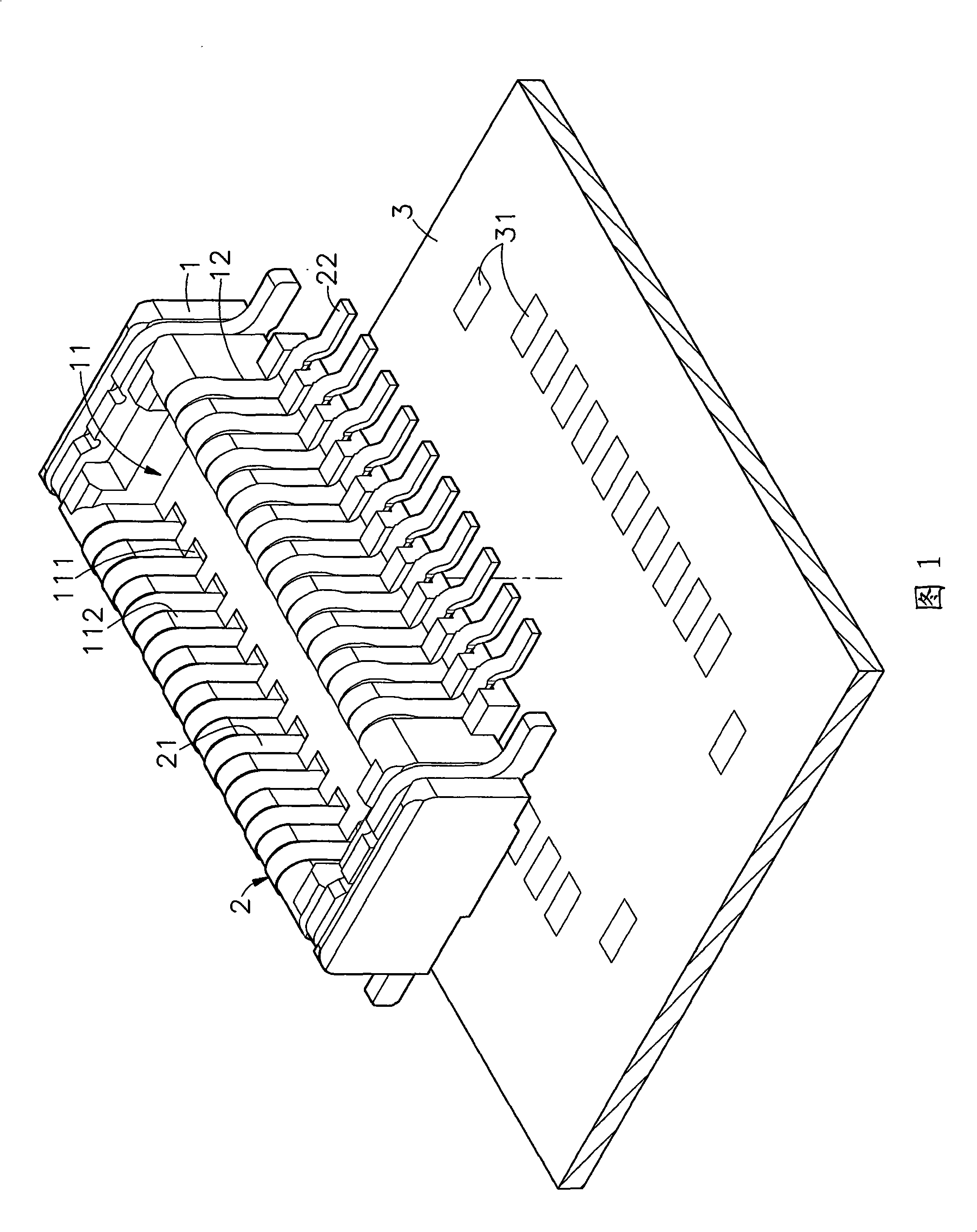
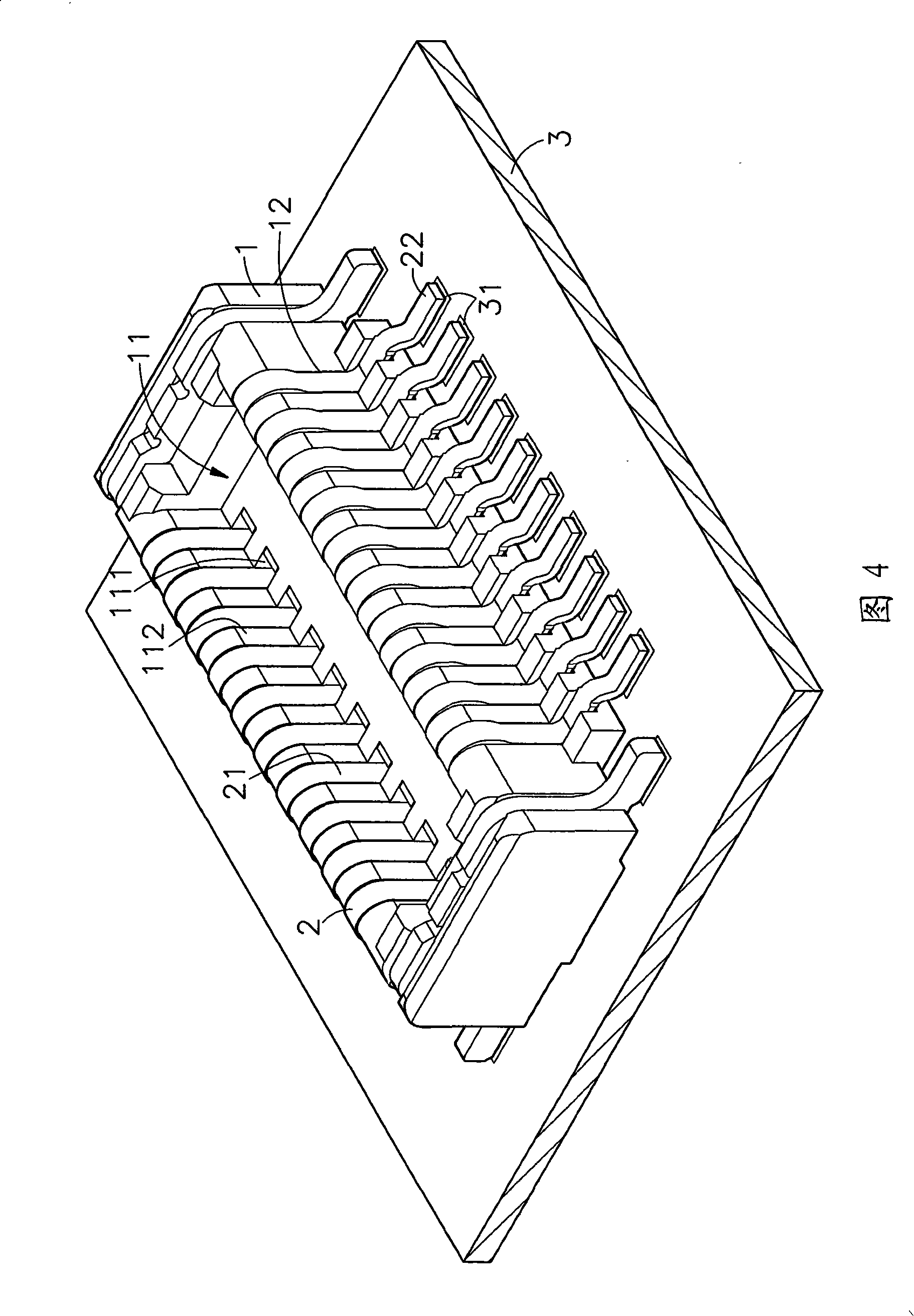
[0034] Please refer to Figures 1 to 3, which are three-dimensional exploded views, side sectional views before etching, and side sectional views after etching of the present invention. It can be clearly seen from the figures that the terminal structure of the present invention is It consists of an insulating base body 1, several terminals 2, etc., among which:

[0035]The insulating seat body 1 has an accommodating space 11 inside, and several slots 111 are arranged in the accommodating space 11, and the wall surface 112 of the accommodating space 11 faces the insulating seat with respect to the several slots 111. The exterior of the body 1 is respectively provided with several clamping grooves 12 .

[0036] The plurality of terminals 2 are provided with a butt joint portion 21 , and a welding portion 22 extends from the butt joint portion 21 to the other side.

[0037] When the above-mentioned components are assembled, several slots 111 in the accommodation space 11 of the i...


PUM


Abstract

The invention provides a terminal structure which can prevent tin bonding; the terminal passes through the slot of an insulated base and extends out of the exterior of the insulated base so as to form a welding part; the appearance of the terminal is processed as an electro-plating layer; the terminal is provided with a naked area which is formed by the laser etching at the internal side of the welding part; furthermore, the naked area is provided with a tin collecting trough which prevents the tin bonding during the welding process of the welding part. Tin liquid is collected when the welding is carried out at the welding part, thus achieving the object of preventing the tin bonded to the terminal and avoiding the short circuit phenomenon of the terminal or the structural change of the terminal.

Description

technical field [0001] The invention relates to a terminal structure, in particular to a connector terminal structure. Background technique [0002] Nowadays, with the rapid development of electronic technology, various electronic products, audio-visual equipment, desktop computers or notebook computers have been ubiquitous in every corner of the society, and the use efficiency is becoming more and more powerful, and the operating speed is also increasing. The main reason is that The industry puts a lot of effort into research and development and enhances product functions. In order to strengthen the operational capabilities of electronic products, more electronic parts and electronic devices are added to electronic products. Due to the increase of various electronic parts and electronic devices, that is, A multi-layer circuit board must be used for the arrangement and layout of various electronic parts and electronic devices. However, if various electronic parts and electro...

Claims


Application Information

Patent Timeline
Patent Type & Authority Applications(China)
IPC IPC(8): H01R12/36H01R12/57
Inventor 陈其昌
Owner 昆山宏致电子有限公司
Why Eureka
Try Eureka