
Electric coupling apparatus of hybrid power machine with dual-coupling mode

A hybrid, electromechanical coupling technology, which is applied in the arrangement of multiple different prime movers of power plants, pneumatic power plants, and general power plants, etc. It takes into account the fuel economy, power and drivability of the whole vehicle, and achieves the effect of convenient space layout, simple and compact structure, and small volume.

Inactive Publication Date: 2009-01-14
DONGFENG ELECTRIC VEHICLE
View PDF2 Cites 13 Cited by
  • Summary
  • Abstract
  • Description
  • Claims
  • Application Information

AI Technical Summary

Problems solved by technology

These two typical solutions have their own advantages and disadvantages, but they cannot take into account the fuel economy, power and drivability of the vehicle well.
Among them, the intermediate shaft coupling scheme has the problems of power interruption and small braking energy feedback when shifting gears. The output shaft coupling scheme cannot realize fast start and stop of the engine, it is difficult to use pure electric power, the torque amplification of the motor is limited, and the energy of the motor and the engine is limited. Allocation optimization is limited and other issues

Method used


Image

  • Electric coupling apparatus of hybrid power machine with dual-coupling mode
  • Electric coupling apparatus of hybrid power machine with dual-coupling mode

Examples


Embodiment Construction

[0008] This embodiment is used to explain the claims, and the protection scope of the present invention is not limited to the following structures.

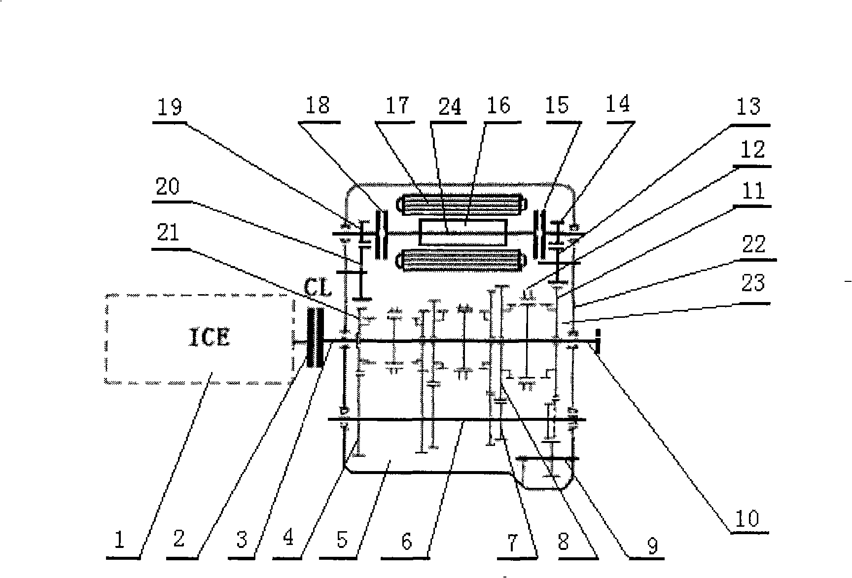
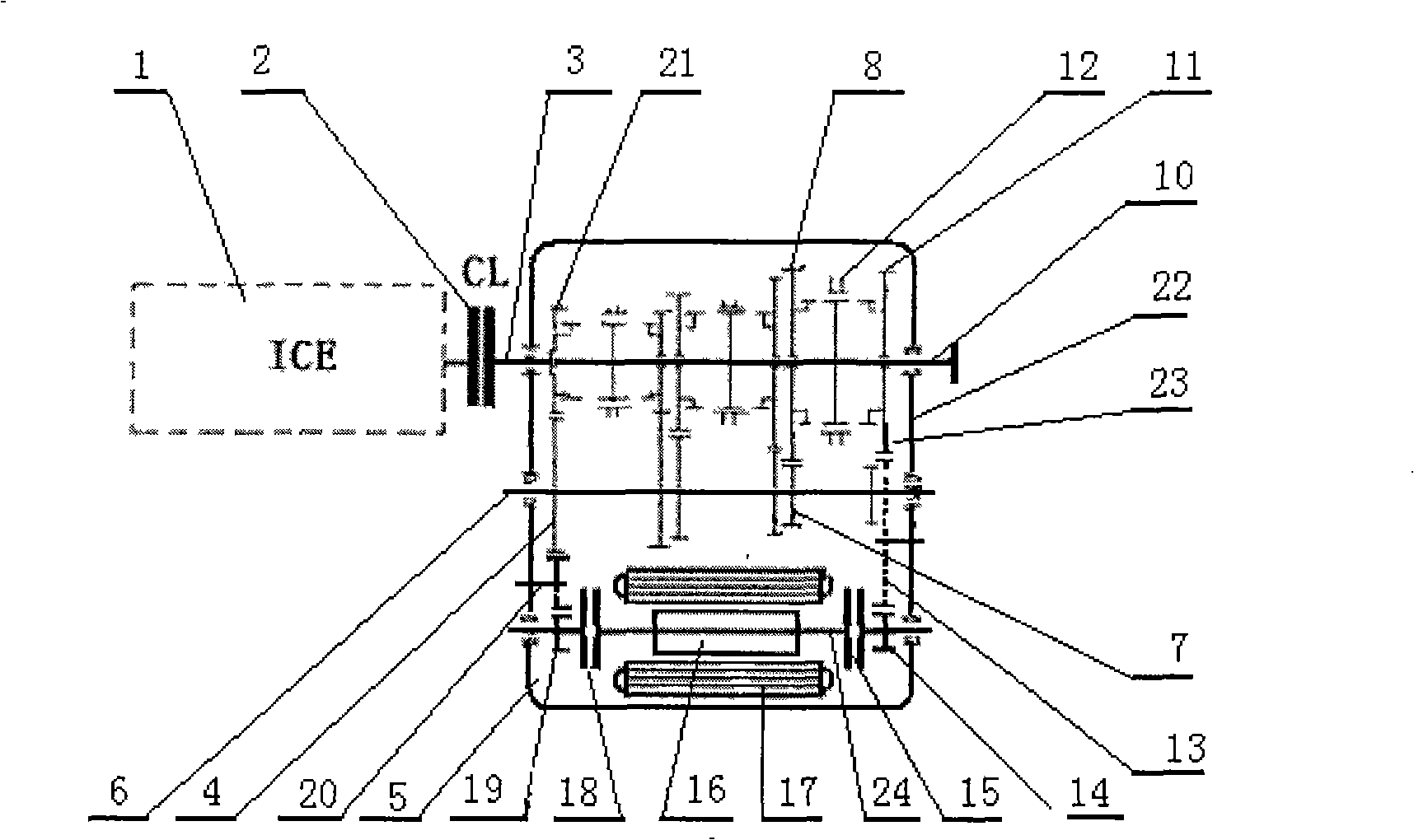
[0009] Such as figure 1 As shown, an engine 1 (not included in the present invention) is connected with an input shaft 3 on a gearbox 5 through a clutch 2 . The gearbox 5 includes a gearbox case 22, and the input shaft 3, the output shaft 10, the intermediate shaft 6 and the reverse gear shaft 9 are arranged in the case body 22, and the speed change gear transmission between the input shaft, the output shaft, the intermediate shaft and the reverse gear shaft Department 23. The speed change gear drive train 23 is similar to the speed change gear drive train in the conventional gearbox, and will not be repeated here.

[0010] A generator / motor stator 17 and a rotor 16 are arranged inside the gearbox case 22 , and the rotor shaft is a bidirectional output shaft 24 . Both ends of the bidirectional output shaft 24 are respectively ...


PUM


Abstract

The invention discloses a double coupling mode hybrid electromechanical coupling device, which comprises a gearbox body, an input shaft, an output shaft, a middle shaft and a reversing shaft which are arranged in the gearbox body, and change gear drive units among the input shaft, the output shaft, the middle shaft and the reversing shaft. The double coupling mode hybrid electromechanical coupling device is characterized in that a two-way output electric generator / motor is arranged in the gearbox body, one end of the output shaft of the two-way output electric generator / motor is connected with a first engaging and disengaging gear, the output shaft of the first engaging and disengaging gear and the input shaft or the middle shaft of the gearbox are formed into a transmission coupling chain through a driving device, the other end of the output axle of the two-way output electric generator / motor is connected with a second engaging and disengaging gear, and the output shaft of the second engaging and disengaging gear and the output shaft of the gearbox are formed into a transmission coupling chain through the driving device. The double coupling mode hybrid electromechanical coupling device adopts the engaging and disengaging gear with simple structure to realize the coupling of the device with the input shaft or the middle shaft of the gearbox or with the output shaft of the gearbox, and can realize the switching among various operating conditions, among the sizes of transmitting energy of each operating condition mode, and among operating condition modes according to the requirements. The device has the advantages that the structure is simple and compact, the volume is small, the spatial arrangement is convenient, and the cost is low.

Description

technical field [0001] The invention belongs to a hybrid power transmission device, in particular to a hybrid electromechanical coupling device of a double coupling mode. Background technique [0002] A hybrid electric vehicle couples the energy of two power sources to meet the requirements of different working conditions. Various existing power coupling devices, some of which are based on the principle of planetary gears, realize the power coupling of internal combustion engines and motors by utilizing multiple degrees of freedom of planetary gears. The disadvantages are complex structures, high costs, and difficulty in popularization. Some are power coupled through clutches and conventional gear mechanisms. The disadvantages are that the integration is not high, the volume is large, and the application is limited. Invention patent application ZL02138754.0, a gearbox for hybrid electric vehicles, announced an intermediate shaft coupling scheme, and utility model patent ZL2...

Claims


Application Information

Patent Timeline
Patent Type & Authority Applications(China)
IPC IPC(8): B60K17/06B60K6/20
Inventor 朱禹徐平兴陈彬刘小燕陈银烛李峥汪振晓
Owner DONGFENG ELECTRIC VEHICLE
Learn More