


Quick Research
Generate reliable direction feasibility study reports for your R&D in just a few steps.

Technical Q&A
Discover and master advanced knowledge NOW. Basics, ideas, possibilities, all at once.

Find Solutions
As an expert in R&D theories, this can generate solutions to your technical problems instantly.

Evaluate Feasibility
Analyze your overall solution with one click, know your potential R&D risks in advance.

Monitor Landscape
Get weekly tech updates, stay abreast of the latest tech innovations and key insights.
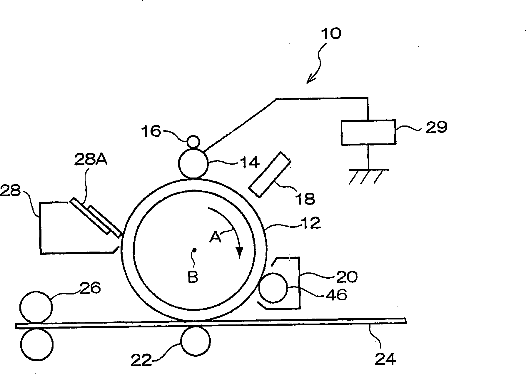
Image forming device
An imaging device and a latent image technology, which are applied in the equipment, electrographic, optical, etc. of the electric recording process applying the charge pattern, to achieve the effects of improving the fluidity, suppressing the image deterioration, and uniforming the toner charge.
- Summary
- Abstract
- Description
- Claims
- Application Information
AI Technical Summary
Problems solved by technology
Method used
Image

Examples
preparation example Construction
[0126] For the preparation of toner mother particles, known wet methods and dry methods can be used. For example, the following methods can be used: a mixing pulverization method in which a binder resin, a colorant and, if necessary, a release agent, a charge control agent, etc. are mixed, pulverized, and classified; A method in the shape of particles; an emulsion polymerization method in which a polymerizable monomer for providing a binder resin is emulsion-polymerized, and the resulting dispersion is mixed with a dispersion in which a coloring agent is dispersed and a release agent and One or more optional dispersions of a charge control agent etc. are mixed and then heated to cause them to aggregate and fuse to obtain a toner; a suspension polymerization method in which a polymerizable monomer for obtaining a binder resin is combined with a colorant and a solution of a release agent and a charge control agent, etc., if necessary, suspended in an aqueous solvent, and polymer...
Embodiment approach
[0226] For the present exemplary embodiment, the "interconnected cell structure" refers to a structure in which a plurality of cells is contained and adjacent gas cells are connected to each other.
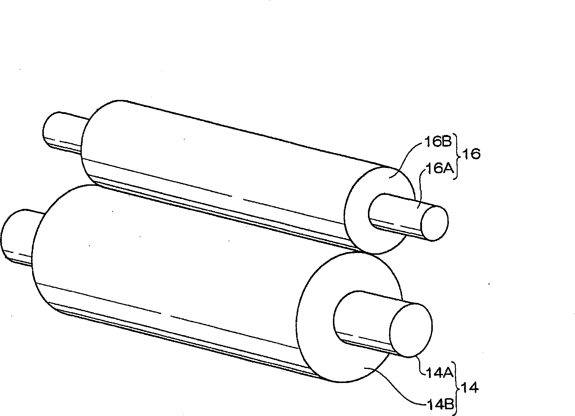
[0227] In addition, for the present exemplary embodiment, "hardness" is measured by the following method. The material constituting the porous layer 16B was cut into a sheet of 400 mm high x 400 mm wide x 50 mm thick, and a load was applied to the central portion of the sliced sheet using a compression jig with a diameter of 200 mm. The force required to compress the thickness by 25% is taken as hardness in the present invention. The force required for compression was measured using a load measuring instrument (MODEL-1311) manufactured by AIKOH.
[0228] The hardness of the porous layer 16B may be 150N-500N, preferably 170N-450N, more preferably 190N-400N. When the hardness is within these ranges, the cleaning roller 16 has sufficient cleaning ability, and inorganic particle a...
Embodiment 1
[0278] Production of Toner A
[0279] ~Preparation of Resin Microparticle Dispersion~
[0280] ·Styrene 296 parts
[0281] · 104 parts of n-butyl acrylate
[0282] · Acrylic acid 6 parts
[0283] · 10 parts of dodecyl mercaptan
[0284] 1.6 parts of divinyl adipate
[0285] (The above are manufactured by Wako Pure Chemical Industries, Ltd.)
[0286] The mixture mixed and dissolved with the above components was added to a mixture consisting of 12 parts of nonionic surfactant (NONIPOL 400, manufactured by Sanyo Chemical Industry Co., Ltd.) and 8 parts of anionic surfactant (NEOGEN SC, manufactured by Daiichi Kogyo Pharmaceutical Co., Ltd. Manufacture) was dissolved in a solution obtained by dissolving 610 parts of ion-exchanged water. It was then dispersed and emulsified in the flask. While mixing slowly for 10 minutes, 50 parts of ion-exchanged water in which 8 parts of ammonium persulfate (manufactured by Wako Pure Chemical Industries, Ltd.) was dissolved was added. Th...
PUM
 Abstract
Description
Claims
Application Information
 - R&D Engineer
- R&D Manager
- IP Professional
- Industry Leading Data Capabilities
- Powerful AI technology
- Patent DNA Extraction
Browse by: Latest US Patents, China's latest patents, Technical Efficacy Thesaurus, Application Domain, Technology Topic, Popular Technical Reports.
© 2024 PatSnap. All rights reserved.Legal|Privacy policy|Modern Slavery Act Transparency Statement|Sitemap|About US| Contact US: help@patsnap.com