


Quick Research
Generate reliable direction feasibility study reports for your R&D in just a few steps.

Technical Q&A
Discover and master advanced knowledge NOW. Basics, ideas, possibilities, all at once.

Find Solutions
As an expert in R&D theories, this can generate solutions to your technical problems instantly.

Evaluate Feasibility
Analyze your overall solution with one click, know your potential R&D risks in advance.

Monitor Landscape
Get weekly tech updates, stay abreast of the latest tech innovations and key insights.
Measuring apparatus
A measuring device and detector technology, which is applied in diagnostic recording/measurement, medical science, mammography, etc., can solve problems such as difficulty in using PAT and limitations in the amount of light in the living body, and achieve the effect of suppressing image degradation
- Summary
- Abstract
- Description
- Claims
- Application Information
AI Technical Summary
Problems solved by technology
Method used
Image

Examples
no. 1 example
[0070] First, a living body information imaging device according to a first embodiment of the present invention will be described.
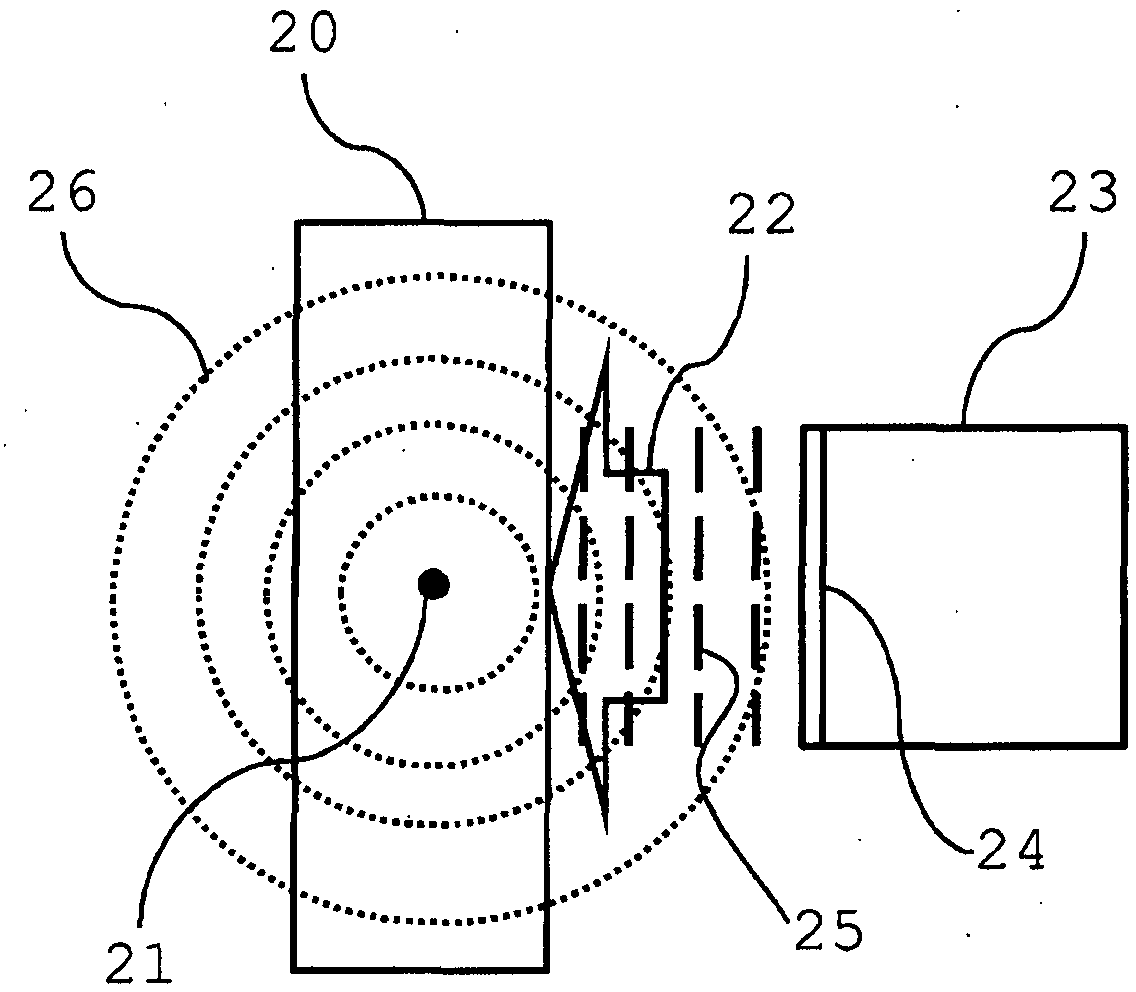
[0071] Figure 5 is a diagram showing a configuration example of the living body information imaging device according to the first embodiment. The living body information imaging device according to the present embodiment is configured to be able to realize distribution of optical property values in a living body, and substances forming body tissues obtained based on such information, for the diagnosis of tumors or vascular diseases, or the subsequent purposes thereof Imaging of the density distribution.
[0072] The living body information imaging device according to the present embodiment has holding units 51 and 52 for holding a living body 50 . The living body 50 held in this way is irradiated with irradiation light 53 .
[0073] The living body information imaging device also has a detector 57 . The detector 57 detects a photoacoustic ...
no. 2 example
[0101] A living body information imaging device according to a second embodiment of the present invention will be described.
[0102] Figure 6 is a diagram showing a configuration example of the living body information imaging device according to the present embodiment. and Figure 5 Those components common to the shown devices are denoted by the same reference numerals, and a detailed description thereof will be omitted.
[0103] The living body information imaging apparatus according to this second embodiment has holding units 60 and 61 for holding a living body 50 . The living body 50 held in this way is irradiated with irradiation light 53 .
[0104] The living body information imaging device also has a detector 57 . The detector 57 detects a photoacoustic wave 55 or a photoacoustic wave 56, which is generated by an optical absorber 54 (such as a tumor, a blood vessel, etc.) etc.), the photoacoustic wave 56 is generated at the surface of the living body.
[0105] Th...
no. 3 example
[0114] A living body information imaging device according to a third embodiment of the present invention will be described.
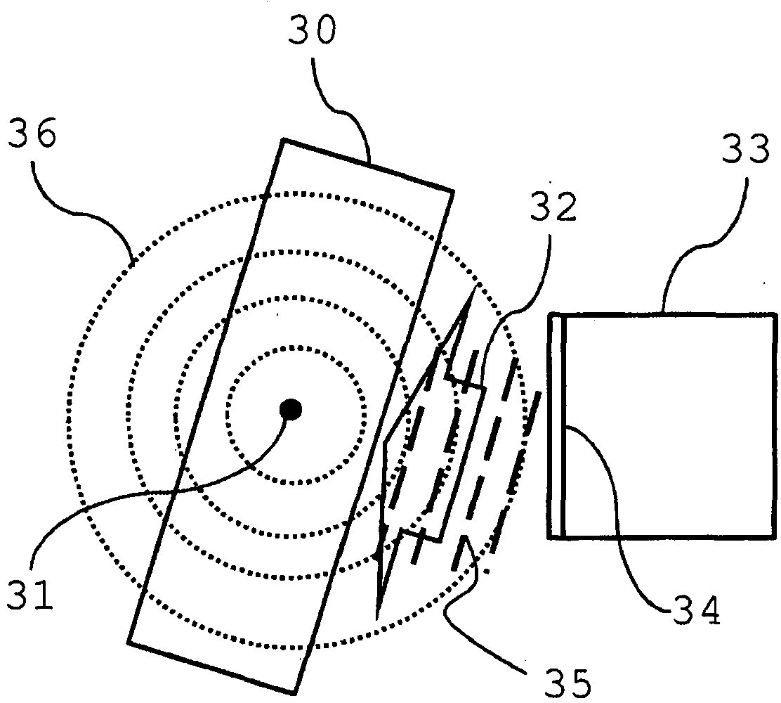
[0115] Figure 7 A configuration example of the living body information imaging device according to the present embodiment is shown. and Figure 5 Those components common to the shown devices are denoted by the same reference numerals, and a detailed description thereof will be omitted.
[0116] The living body information imaging device according to the present embodiment has holding units 70 and 71 for holding the living body 50 . The living body 50 held in this way is irradiated with irradiation light 53 .
[0117] The living body information imaging device also has a detector 57 that detects a photoacoustic wave 55 or a photoacoustic wave 56 and converts the detected photoacoustic wave into an electrical signal. Generated by a tumor, blood vessel, or such other optical absorber 54, the photoacoustic waves 56 are generated at the surface of the l...
PUM
 Abstract
Description
Claims
Application Information
 - R&D Engineer
- R&D Manager
- IP Professional
- Industry Leading Data Capabilities
- Powerful AI technology
- Patent DNA Extraction
Browse by: Latest US Patents, China's latest patents, Technical Efficacy Thesaurus, Application Domain, Technology Topic, Popular Technical Reports.
© 2024 PatSnap. All rights reserved.Legal|Privacy policy|Modern Slavery Act Transparency Statement|Sitemap|About US| Contact US: help@patsnap.com