


Quick Research
Generate reliable direction feasibility study reports for your R&D in just a few steps.

Technical Q&A
Discover and master advanced knowledge NOW. Basics, ideas, possibilities, all at once.

Find Solutions
As an expert in R&D theories, this can generate solutions to your technical problems instantly.

Evaluate Feasibility
Analyze your overall solution with one click, know your potential R&D risks in advance.

Monitor Landscape
Get weekly tech updates, stay abreast of the latest tech innovations and key insights.
Liquid crystal display device
a display device and liquid crystal technology, applied in static indicating devices, non-linear optics, instruments, etc., can solve the problems of reducing the life of liquid crystals, affecting the display quality, and affecting the image quality, so as to achieve high-quality images and suppress image degradation
- Summary
- Abstract
- Description
- Claims
- Application Information
AI Technical Summary
Benefits of technology
Problems solved by technology
Method used
Image

Examples
first embodiment
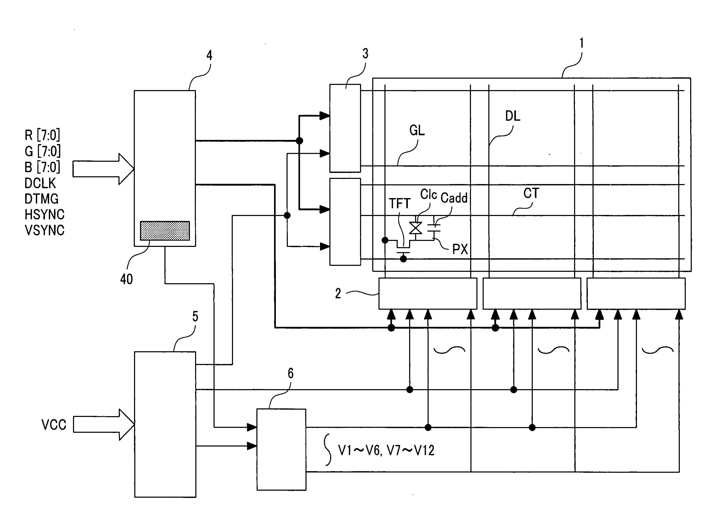
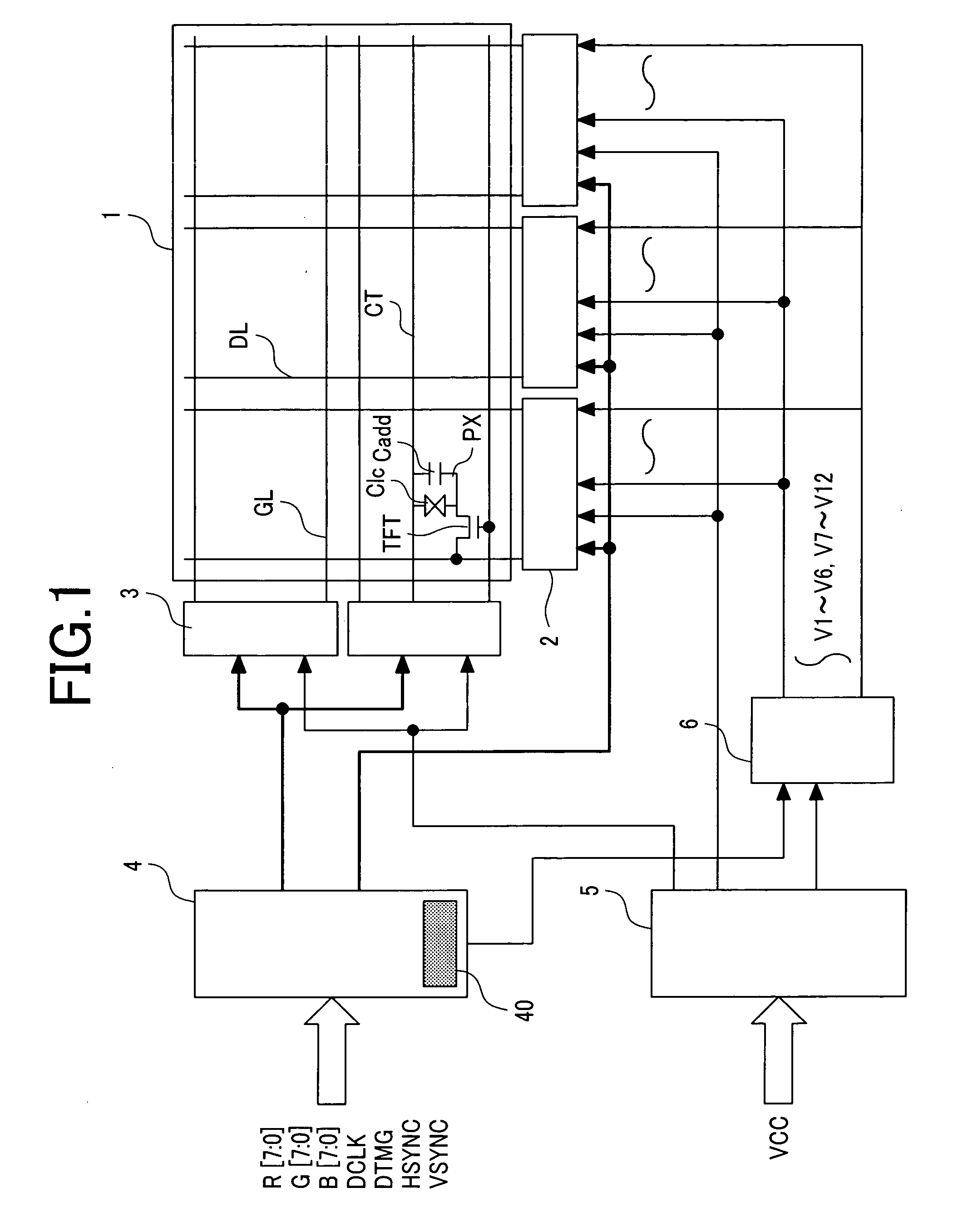
[0061]FIG. 1 is a block diagram showing a schematic configuration of a liquid crystal display module according to a first embodiment of the present invention. The liquid crystal display module according to this embodiment includes a liquid crystal display panel 1, a drain driver 2, a gate driver 3, a display control circuit (timing controller) 4, a power supply circuit 5, and a gray-scale reference voltage generation circuit 6.
[0062]The drain driver 2 includes semiconductor chips disposed near one edge of the liquid crystal panel 1, and the gate driver 3 includes semiconductor chips disposed near another edge thereof.
[0063]A display control circuit 4 includes a memory (e.g., electronically erasable and programmable read-only memory (EEPROM)) 40, and timing-adjusts display data (R [7:0], G [7:0], B [7:0]) inputted from a display signal source (host) such as a television reception circuit, according to a dot clock (DCLK), a display timing signal (DTMG), a horizontal synchronizing sign...
second embodiment
[0118]FIG. 7 is a block diagram showing a schematic configuration of a liquid crystal display module according to a second embodiment of the present invention. The configuration of the liquid crystal display module according to this embodiment is similar to that according to the above-mentioned first embodiment except that the liquid crystal display panel 1 according to this embodiment includes a temperature detector 41.
[0119]The configuration of this embodiment will now be described, focusing on the difference between this embodiment and the above-mentioned embodiment. The temperature detector 41 may be provided on a printed wiring board, for example, on that on which the display control circuit 4 is mounted.
[0120]In general, the response of the liquid crystal particles is influenced by the temperature. Therefore, the optimal value of the correction voltage indicated by the ΔVa of FIG. 6 varies with the temperature.
[0121]In this embodiment, the temperature of the liquid crystal dis...
third embodiment
[0131]FIG. 17 is a diagram showing the reason why flicker occurs in the first frame immediately after a phase inversion in a case where the phase inversion drive method shown in FIG. 6 is used. In other words, FIG. 17 is a diagram showing an image voltage written to a subpixel in the first frame immediately after a phase inversion in a case where the phase inversion drive method shown in FIG. 6 is used and an image voltage written to a subpixel in a case where the AC drive method shown in FIG. 12 is used.
[0132]In the AC drive method shown in FIG. 12, the voltage of a subpixel changes from a positive image voltage to a negative image voltage or from a negative image voltage to a positive image voltage each time the current alternates. On the other hand, if a subpixel has continuous identical polarities such as (−) (−)→(−) (−) or (+) (+)→(+) (+) by using the phase inversion drive method shown in FIG. 6, the voltage of the subpixel changes from a positive image voltage to another posit...
PUM
 Abstract
Description
Claims
Application Information
 - R&D Engineer
- R&D Manager
- IP Professional
- Industry Leading Data Capabilities
- Powerful AI technology
- Patent DNA Extraction
Browse by: Latest US Patents, China's latest patents, Technical Efficacy Thesaurus, Application Domain, Technology Topic, Popular Technical Reports.
© 2024 PatSnap. All rights reserved.Legal|Privacy policy|Modern Slavery Act Transparency Statement|Sitemap|About US| Contact US: help@patsnap.com