


Quick Research
Generate reliable direction feasibility study reports for your R&D in just a few steps.

Technical Q&A
Discover and master advanced knowledge NOW. Basics, ideas, possibilities, all at once.

Find Solutions
As an expert in R&D theories, this can generate solutions to your technical problems instantly.

Evaluate Feasibility
Analyze your overall solution with one click, know your potential R&D risks in advance.

Monitor Landscape
Get weekly tech updates, stay abreast of the latest tech innovations and key insights.
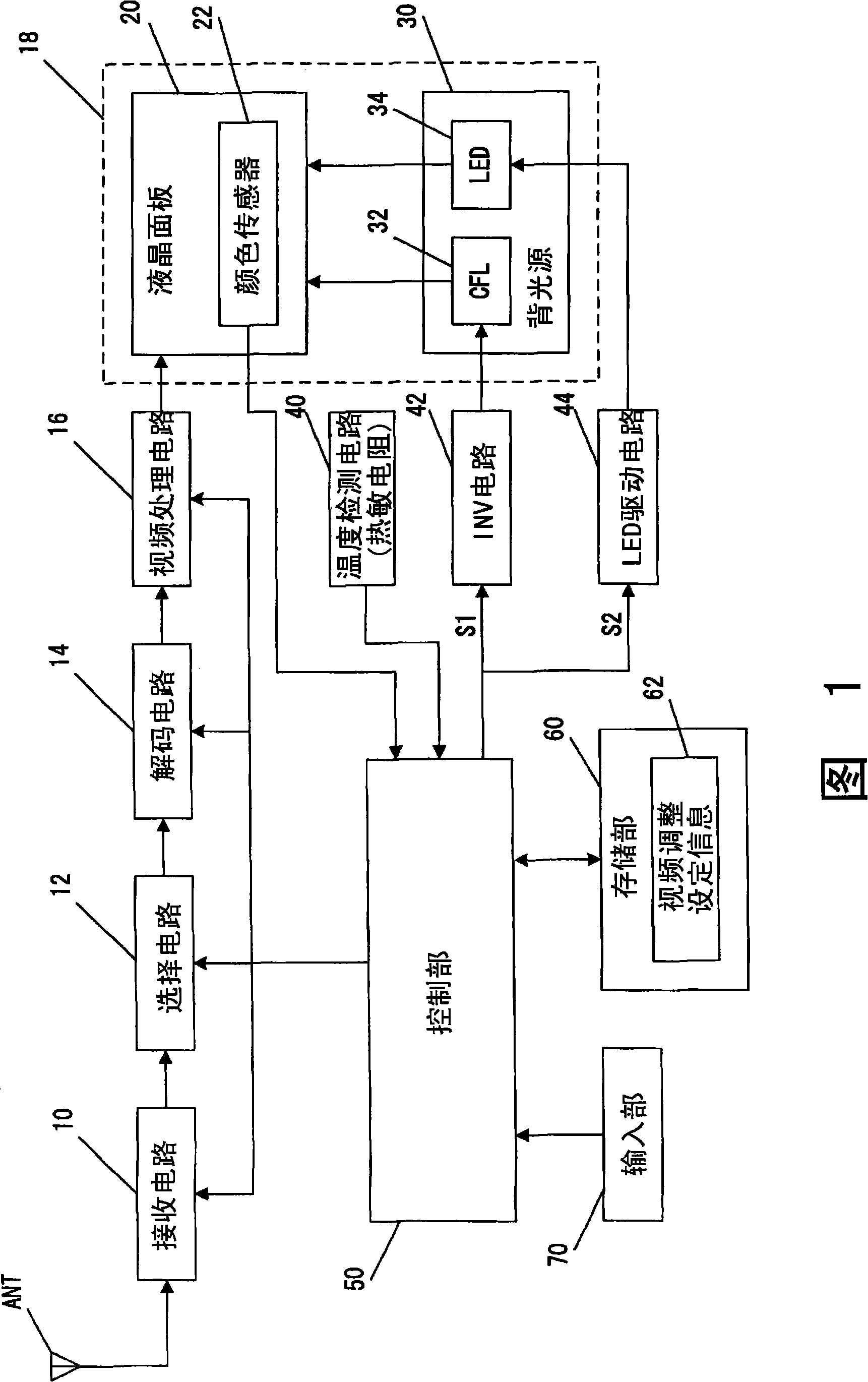
Backlight device and liquid crystal display device
A liquid crystal display device and backlight technology, applied in the direction of light source, electric light source, electric light source, etc., can solve problems such as brightness difference and uneven brightness, and achieve the effect of eliminating uneven brightness or uneven color
- Summary
- Abstract
- Description
- Claims
- Application Information
AI Technical Summary
Problems solved by technology
Method used
Image

Examples
Embodiment 3
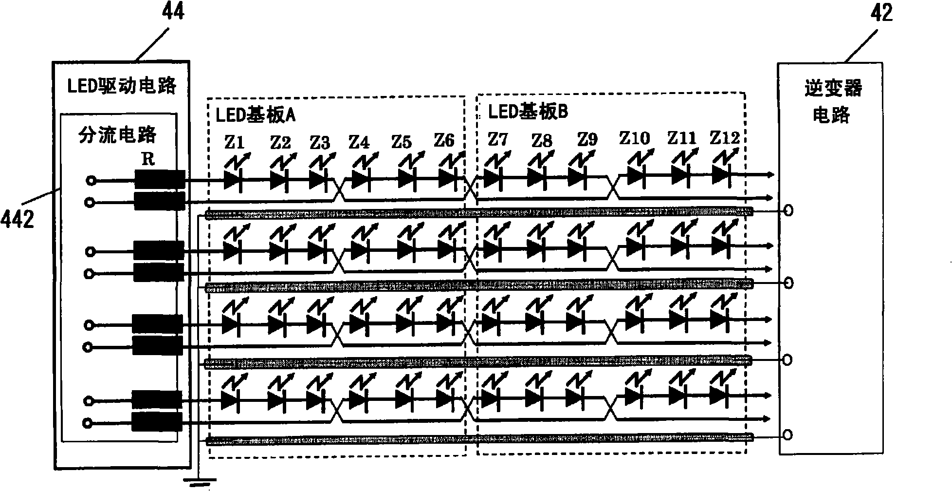
[0101] FIG. 7 shows a configuration example in which LED arrays of one line connected in series are arranged in a twisted shape as Embodiment 4 of the present invention.
[0102] As a specific configuration, a plurality of LEDs connected in series via a flexible cable are arranged across two columns from one side coil constituted by a drive circuit board-shaped shunt circuit. Then, connect three LEDs (Z1 to 3) connected in series from the end of the first column on the substrate, and the second LED located in the horizontal direction (the direction in which LEDs that are continuously connected in series in the same column) to the LEDs. The three series-connected LEDs (Z4-6) of the columns are electrically connected, and then connected to the LEDs (Z7-) of the first column.
[0103] Using this as a repeating unit, after many (N) times of LEDs are connected in series in the horizontal direction, the direction of the polarity of the previous LEDs is reversed through the wiring pa...
Embodiment 4
[0107] Next, Embodiment 4 of the present invention shown in FIG. 8 will be described.
[0108] In this embodiment, the example shown is to make the aforementioned embodiment 1 ( Figure 4 ) extension, for the LED array mounting row provided to mount a plurality of LEDs in a row on the LED substrate, the 2-wire part of the LED array connected in series from each coil of the shunt circuit is alternately exchanged with respect to the parallel direction of the mounting row Each line has a turn-back portion, and for other LED array mounting columns on the LED substrate, the parallel direction of each LED line relative to the mounting column is alternately mounted.
[0109] That is, the two coils 442a and 442b of the shunt circuit 442 are connected to terminals provided at the ends of the LED substrate, and the coil 442a on one side is connected in series to three consecutive LEDs (Z1-3) from the end of the first row. connect. The coil 442b on the other side connects the LEDs (Z4-...
Embodiment 5
[0114] FIG. 9 illustrates another embodiment 5 related to the present invention.
[0115] In this embodiment, the example shown is the same as Embodiment 4, so that the aforementioned Embodiment 1 ( Figure 4 ) extension. Specifically, for two parallel LED array mounting rows provided to mount a plurality of LEDs in a row on the LED substrate, the two-wire part of the LED array connected in series to each coil of the shunt circuit is compared to the parallel arrangement of each row. The direction is alternately exchanged, and each line has a turn-back portion. For the LED array installation columns with two parallel columns on the LED substrate, the parallel direction of each LED line relative to each column is alternately installed.
[0116] That is, the two coils 442a and 442b of the shunt circuit 442 are connected to terminals provided at the ends of the LED substrate, and the coil 442a on one side is connected in series to three consecutive LEDs (Z1-3) from the end of the...
PUM
 Abstract
Description
Claims
Application Information
 - R&D Engineer
- R&D Manager
- IP Professional
- Industry Leading Data Capabilities
- Powerful AI technology
- Patent DNA Extraction
Browse by: Latest US Patents, China's latest patents, Technical Efficacy Thesaurus, Application Domain, Technology Topic, Popular Technical Reports.
© 2024 PatSnap. All rights reserved.Legal|Privacy policy|Modern Slavery Act Transparency Statement|Sitemap|About US| Contact US: help@patsnap.com