
Bottle cap glue-injection machine

A technology of glue injection machine and bottle cap, which is applied to other household appliances, household appliances, household components, etc., to improve the efficiency of glue injection, prevent secondary pollution, and reduce waste rate.

Active Publication Date: 2010-06-02
SUZHOU HYCAN HLDG CO LTD
View PDF0 Cites 4 Cited by
  • Summary
  • Abstract
  • Description
  • Claims
  • Application Information

AI Technical Summary

Problems solved by technology

[0003] The purpose of the present invention is to provide a fully automatic bottle cap glue injection machine with high efficiency and good product quality, which can well solve the problems caused by manual glue injection operation

Method used


Image

  • Bottle cap glue-injection machine
  • Bottle cap glue-injection machine

Examples


Embodiment Construction

[0009] The bottle cap glue injection machine of the present invention will be further described below in conjunction with the accompanying drawings.

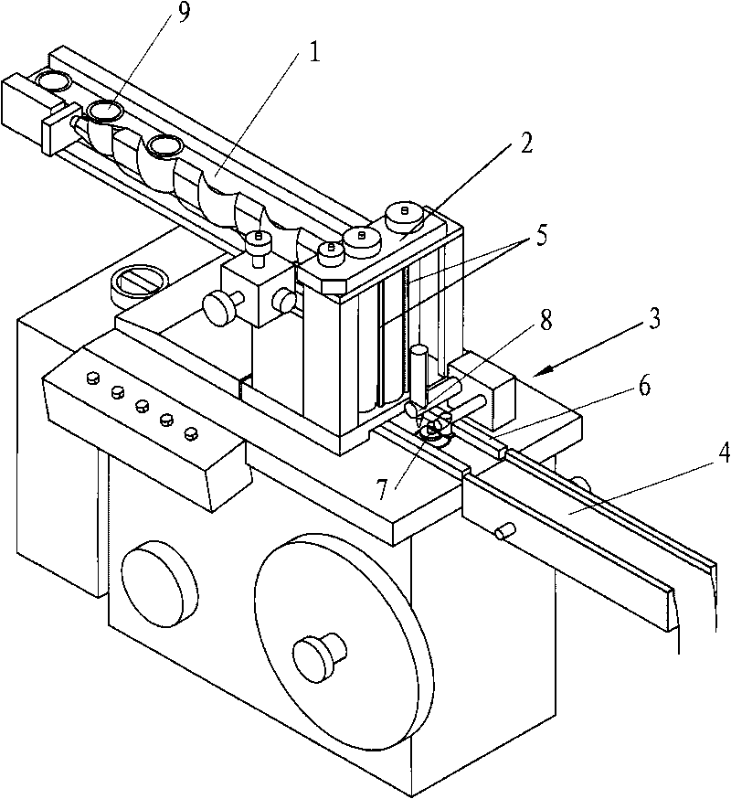
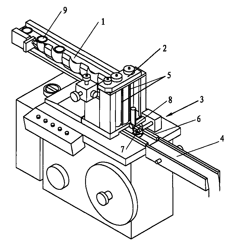
[0010] as attached figure 1 Shown, a kind of bottle cap injection machine, it comprises input assembly line 1, output assembly line 4, sub-cap device 2, injection device 3, described injection device 3 comprises the manipulator 6 for moving bottle cap, for The sensor 7 for detecting the position of the bottle cap and the injection mold 8 for injecting glue on the bottle cap, the sensor 7 is connected to the glue injection device 8 with a signal, and the upper end of the cap splitting device 2 is connected to the input The assembly line 1 is connected, and the lower end is connected with the glue injection device 3. The cover sub-device 2 includes two completely identical lead screws 5 vertically placed and parallel to each other. The two lead screws 5 are The direction of rotation and the speed of rotation are the same, the dis...


PUM


Abstract

The invention relates to a bottle cup glue-injection machine, comprising an input production line, an output production line, a cap separating device and a glue-injection device, the upper end of the cap separating device is connected with the input production line, and the lower end thereof is connected with the glue-injection device, the cap separating device comprises two same leading screws which are vertically arranged and are parallel, the rotating direction and the rotating speed of two leading screws are the same, the distance between top parts of screw threads of two leading screws is less than the diameter of a bottle cap to be processed, and the distance between the bottom parts of screw threads of two leading screws is greater than the diameter of the bottle cap to be processed. The application of the bottle cap glue-injection machine greatly increases the glue-injection efficiency, the reject rate of the product is reduced, and the secondary pollution of the product and the phenomena of uneven and non-flat glue surface of a product are basically eradicated.

Description

technical field [0001] The invention relates to a bottle cap glue injection machine. Background technique [0002] In the prior art, due to the special structure of the bottle cap product, it cannot be processed on a conventional glue injection machine, and the glue injection operation is completely manual. Full manual operation has high labor intensity, low output, uneven rubber surface, and unstable sealing performance; and according to the requirements of product hygiene level, manual operation is easy to cause secondary pollution to the product, the difficulty of hygiene management is high, and the quality of the finished product is not guaranteed. . Contents of the invention [0003] The object of the present invention is to provide a fully automatic bottle cap glue injection machine with high efficiency and good product quality, which can well solve the problems caused by manual glue injection operation. [0004] The technical solution adopted by the present invent...

Claims


Application Information

Patent Timeline
Patent Type & Authority Applications(China)
IPC IPC(8): B29D99/00
Inventor 李炳兴
Owner SUZHOU HYCAN HLDG CO LTD
Learn More