
Flue gas waste heat recovery system of metallurgy electric furnace

A flue gas waste heat recovery system technology, applied in preheating, feed water heaters, lighting and heating equipment, etc., can solve the problems of low hot water taste and low utilization efficiency, and achieve the effect of improving utilization efficiency and good utilization

Inactive Publication Date: 2008-12-03
BEIJING BOOTES ELECTRIC POWER SCI & TECH
View PDF0 Cites 15 Cited by
  • Summary
  • Abstract
  • Description
  • Claims
  • Application Information

AI Technical Summary

Problems solved by technology

This is because the temperature in the metallurgical electric furnace is usually above 1000 degrees Celsius, while the temperature of the circulating cooling water is lower than 100 degrees Celsius. Even if the heat of hot water is utilized, the taste of hot water is low, so the utilization efficiency is extremely low

Method used


Image

  • Flue gas waste heat recovery system of metallurgy electric furnace

Examples


Embodiment Construction

[0010] Preferred embodiments of the present invention will be described below with reference to the drawings.

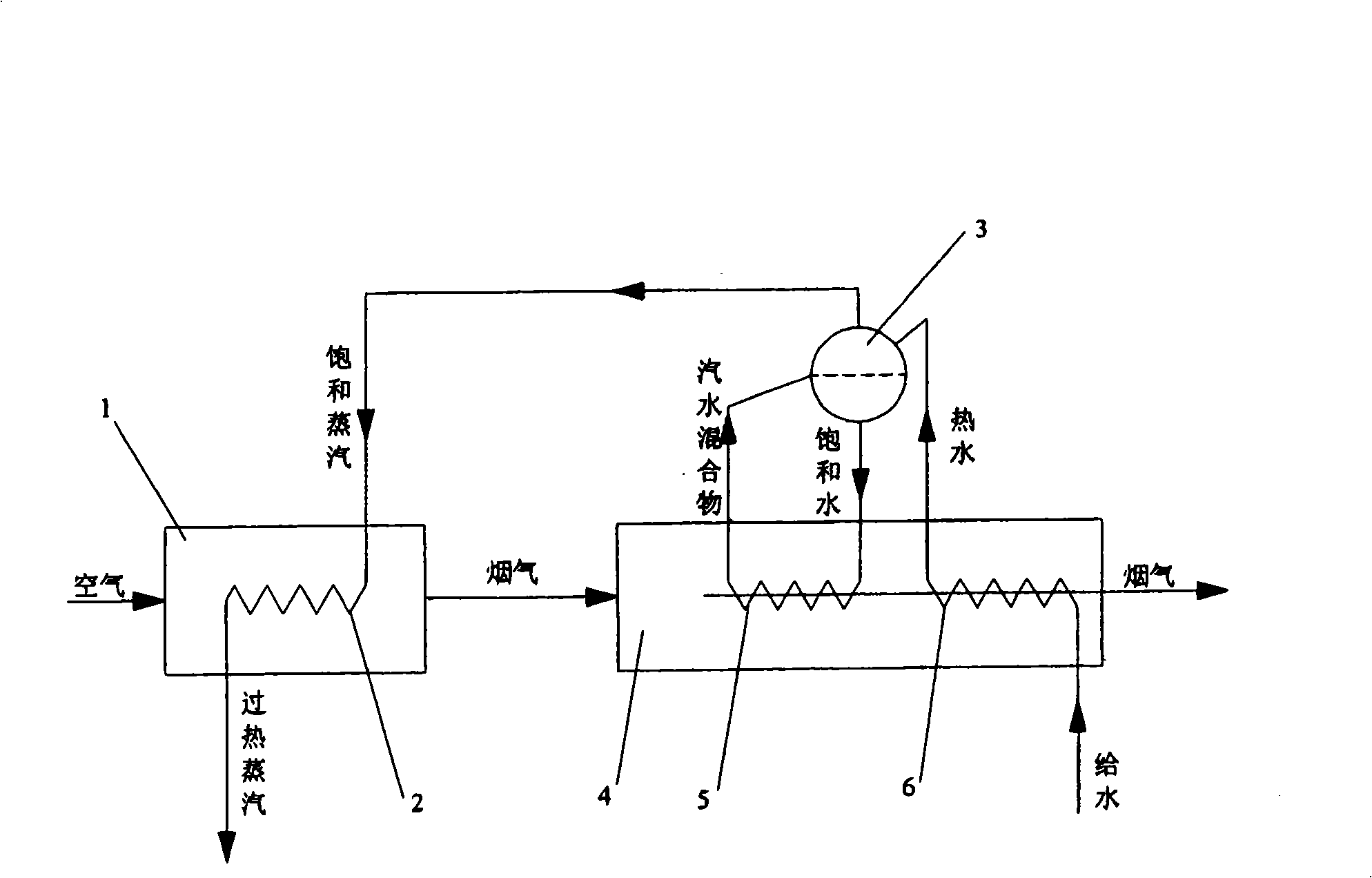
[0011] Such as figure 1 As shown, the flue gas discharged from the electric furnace 1 is introduced into the waste heat boiler 4 provided outside the electric furnace 1 . The waste heat boiler 4 is provided with an evaporative heating surface 5 and an economizer 6. During the process of flowing through the evaporating heating surface 5 and the economizer 6, the flue gas conducts convective heat exchange with the water flowing therein, so that the heat is recovered, and the temperature reduce. Both the evaporation heating surface 5 and the economizer 6 adopt known structures, and their detailed descriptions are omitted here.

[0012] Furthermore, a steam drum 3 is provided on the top of the waste heat boiler 4, and the structure of the steam drum 3 is also known, so its detailed description will be omitted here. The steam drum 3 is connected to the outlet of the ec...


PUM


Abstract

The invention provides a metallurgic electric furnace flue gas waste heat recovery system for realizing high-efficiency recovery of waste heat of a metallurgic electric furnace. The system comprises a waste heat boiler (4). The waste heat boiler is arranged outside an electric furnace (1). The flue gas exhaust from the electric furnace is guided into the waste heat boiler. The waste heat boiler comprises an evaporation heating surface (5), a coal economizer (6) and a steam tank (3). The coal economizer supplies water to the waste heat boiler. The hot water flowing out of the exit of the coal economizer is supplied to the steam tank. The bottom of the steam tank is connected with the entrance of the evaporation heating surface. The steam tank supplies saturated water to the evaporation heating surface. The middle part of the steam tank is connected with the exit of the evaporation heating surface. The steam-water mixture enters the steam tank after heat absorption and undergoes steam-water separation in the steam tank. The system further comprises a radiation heating surface which is arranged inside the electric furnace. The entrance of the radiation heating surface is connected with the steam tank. The saturated steam inside the steam tank flows to the radiation heating surface, the radiation heating surface absorbs the high-temperature radiation heat inside the electric furnace and heats the saturated steam to form superheated steam, and the superheated steam is guided out of the exit of the radiation heating surface.

Description

technical field [0001] The invention relates to a waste heat recovery system of metallurgical electric furnace flue gas. Background technique [0002] Metallurgical electric furnaces use electricity as the main energy source and semi-coke as one of the main raw materials. During the metal smelting process, a large amount of heat will be released, most of which are taken out of the furnace by the flue gas for discharge, and part of the heat is taken away by the circulating cooling water in the electric furnace. The heat recovered by the conventional waste heat recovery device (waste heat boiler) is only the heat of the flue gas, and the heat absorbed by the circulating cooling water in the furnace is given up for recovery. The purpose of setting the circulating cooling water heating surface in the electric furnace is to protect the furnace wall. If the circulating cooling water is not installed, the high-temperature radiation heat generated during the smelting process of the...

Claims


Application Information

Patent Timeline
IPC IPC(8): F22D1/08F22D7/00F22B1/18F22D1/00
Inventor 李永旺吴树志张明
Owner BEIJING BOOTES ELECTRIC POWER SCI & TECH
Learn More