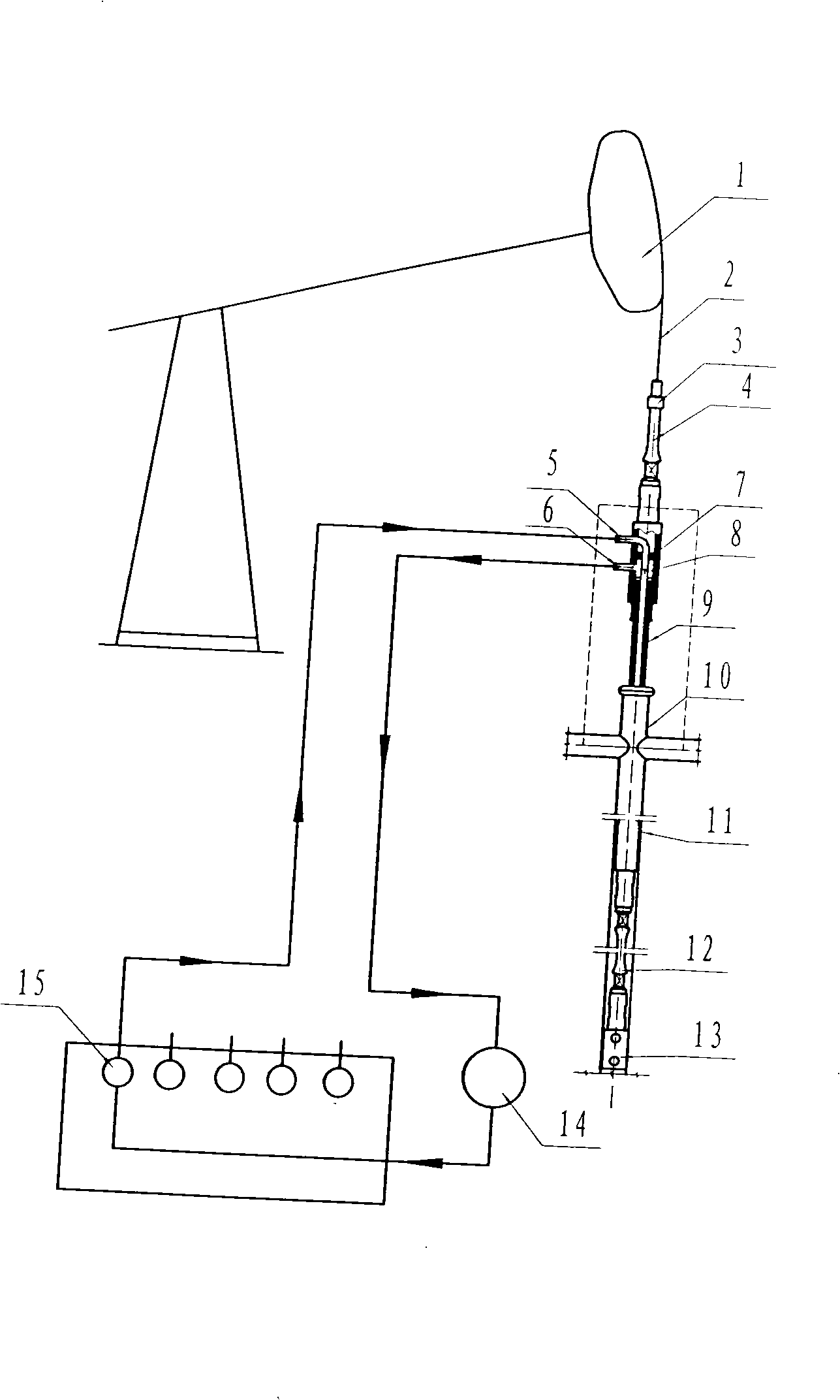
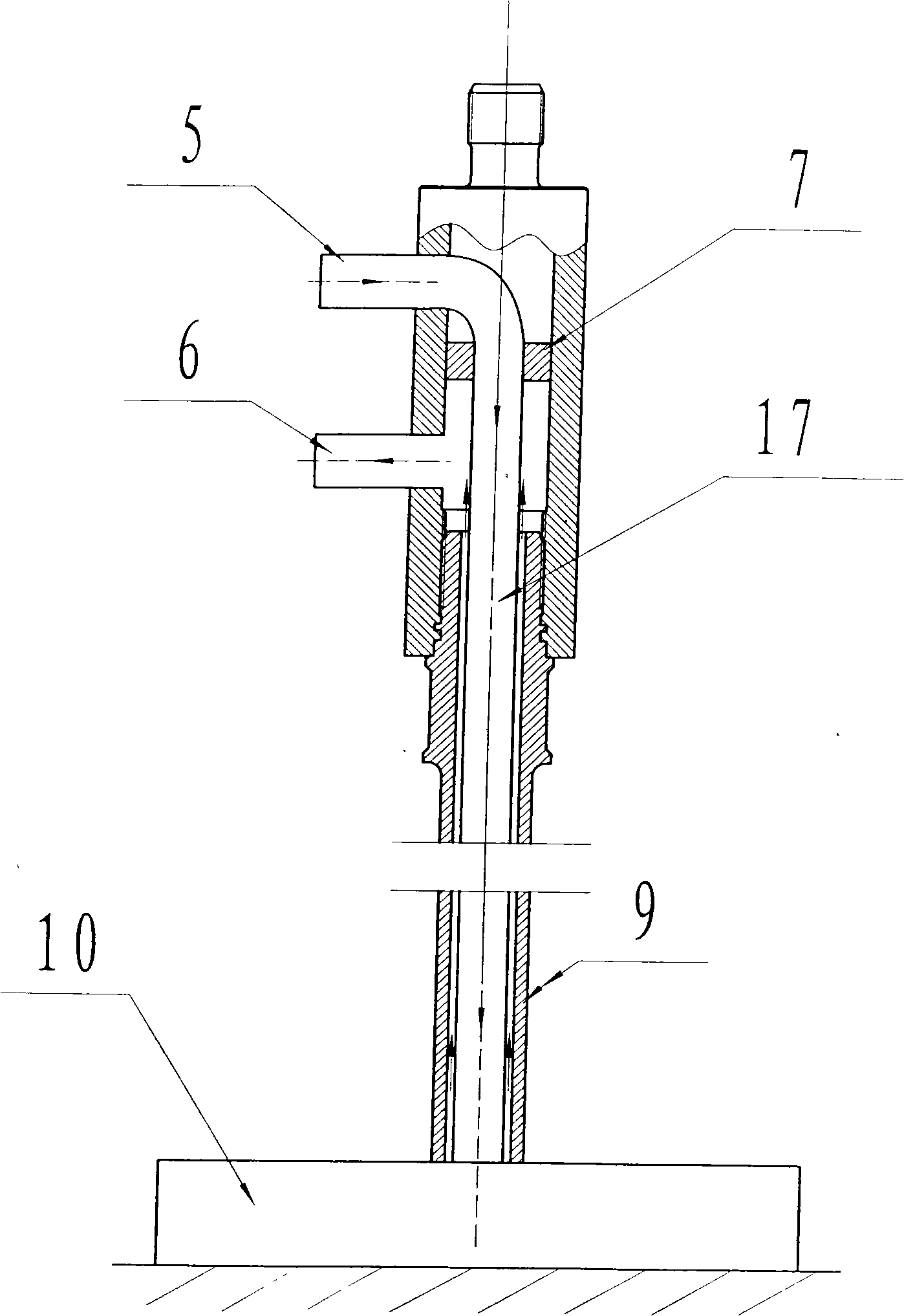
Thick oil well bore heating and viscosity reducing hot extraction method and apparatus
An oil well and viscosity reduction technology, which is applied in the direction of production fluid, earthwork drilling, wellbore/well components, etc., can solve the problems of inaccurate calculation of oil volume, difficulty in restoring production, non-durability, etc., to save energy and equipment The effect of investment, avoiding high cost and long service life
Inactive Publication Date: 2008-10-22
胜利油田孚瑞特石油装备有限责任公司 +1
View PDF0 Cites 4 Cited by
- Summary
- Abstract
- Description
- Claims
- Application Information
AI Technical Summary
Problems solved by technology
At present, there are more and more mechanical wells in the oil field with high pour point and heavy oil, and the use of conventional development technology has seriously affected the liquid output
In order to solve this problem, various oilfields have adopted different thermal recovery technologies, but the results are not ideal
For example, the application of electric heating pipe rod is to put a single-core cable into the hollow sucker rod to form a heating cable for the electric circuit, and use variable frequency power supply, DC pulse power supply, and three-phase power adjustment power supply to supply power respectively. This technology consumes high power and costs high
The technology of adding hot water into the hollow rod directly injects hot water into the downhole tubing through the hollow sucker rod. Although it is easy to use, it is easy to scale inside the hollow rod. The added water flows out together with the oil, and the oil volume cannot be accurately calculated. And high energy consumption, long process, high input cost
The method of adding chemical agent to reduce viscosity is to add chemical agent to the downhole casing and tubing annulus to reduce viscosity, which greatly increases the production cost of oil production, and the injection of chemical agent by single well dosing pump is limited by the high pressure of the casing, so it cannot Durable, heavy workload, high maintenance cost, not timely dosing will cause well shutdown, difficult to resume production, and pollute the environment
Method used
View moreImage
Smart ImageViewing Examples
Examples
Embodiment Construction
Login to View More PUM
 Abstract
The invention relates to a viscous oil pitshaft heating and thinning thermal excavation method and a device using the same. The method is as follows: a hollow sucker rod is sleeved with an insulating tube and two thermal cycling tunnels are formed, an external circulation pipe line is connected to a heating furnace and a circulating pump in sequence, and then continuous closed thermal cycling exchanged heating is formed. The device comprises an oil extractor, a polished rod eye, a polished rod clamp, a polished rod connector, the hollow sucker rod, a wellhead device, an oil well pump, the heating furnace, the circulating pump and a circulation pipe line, wherein the hollow polished rod connector is provided with a connecting device, and the insulating tube of the hollow sucker rod and the two thermal cycling tunnels at outer annular space are respectively abutted with the external circulation pipe line through the connecting device. The technology adopts the method that a proper annular clearance is left between the hollow sucker rod and the insulating tube, a closed circulating independent heating system is formed, thereby saving energy, operating conveniently, and being safe, reliable, and long in service life.
Description
Thermal recovery method and device for heavy oil wellbore heating and viscosity reduction technical field The invention relates to a heavy oil wellbore heating and viscosity-reducing thermal recovery method and device in the technical field of oilfield crude oil thermal recovery. Background technique At present, there are more and more mechanical recovery wells for high-condensation and heavy oil in oilfields, and the use of conventional development technology has seriously affected the fluid output. In order to solve this problem, various oilfields have adopted different thermal recovery technologies, but the effects are not satisfactory. For example, the application of electric heating pipe rod is to put a single-core cable into the hollow sucker rod to form a heating cable for the electric circuit, and use variable frequency power supply, DC pulse power supply, and three-phase power adjustment power supply to supply power respectively. This technology consumes high powe...
Claims
Login to View More Application Information
Patent Timeline
 Patent Type & Authority Applications(China)
IPC IPC(8): E21B43/24
Inventor 刘国庆吴德奇周尔洲王江秀李永张力王基伟
Owner 胜利油田孚瑞特石油装备有限责任公司
Features
- R&D
- Intellectual Property
- Life Sciences
- Materials
- Tech Scout
- Unparalleled Data Quality
- Higher Quality Content
- 60% Fewer Hallucinations
Learn More Browse by: Latest US Patents, China's latest patents, Technical Efficacy Thesaurus, Application Domain, Technology Topic, Popular Technical Reports.
© 2025 PatSnap. All rights reserved.Legal|Privacy policy|Modern Slavery Act Transparency Statement|Sitemap|About US| Contact US: help@patsnap.com


