Boring tool and method of boring pilot hole

A hole processing and pre-drilling technology, which is applied in the direction of manufacturing tools, metal processing equipment, hole reaming devices, etc., can solve the problems of high production cost of reamers, high cutting resistance, and inability to supply cutting oil, etc.

Inactive Publication Date: 2008-10-08
MITSUBISHI MATERIALS CORP
View PDF2 Cites 6 Cited by
  • Summary
  • Abstract
  • Description
  • Claims
  • Application Information

AI Technical Summary

Problems solved by technology

[0021] However, in Figure 21 and Figure 22 In the conventional reamer shown, although the chips are discharged toward the front end of the reamer so that they do not pass through the chip discharge grooves, the chip discharge grooves are still formed so that they have a V-shaped cross section and are widely opened radially outward.
On the other hand, when the chip discharge groove is formed by cutting off the cutting edge portion in this way, there is a problem that the rigidity of the reamer decreases, vibration occurs when the reamer rotates at high speed, and the hole cannot be formed with high precision.
Therefore, only reamers in which the coolant supply hole in the shank and the communication hole in the tip are the same diameter can be produced, so the cutting oil cannot be sufficiently supplied to the workpiece.
[0026] In addition, in the case of cutting a relatively hard material to be cut, it is necessary to use a harder cemented carbide to form the tip of the tool, but in the case of integral sintering, since even t...

Method used


Image

  • Boring tool and method of boring pilot hole
  • Boring tool and method of boring pilot hole
  • Boring tool and method of boring pilot hole

Examples


Embodiment Construction

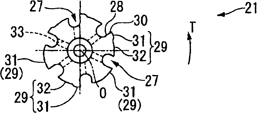
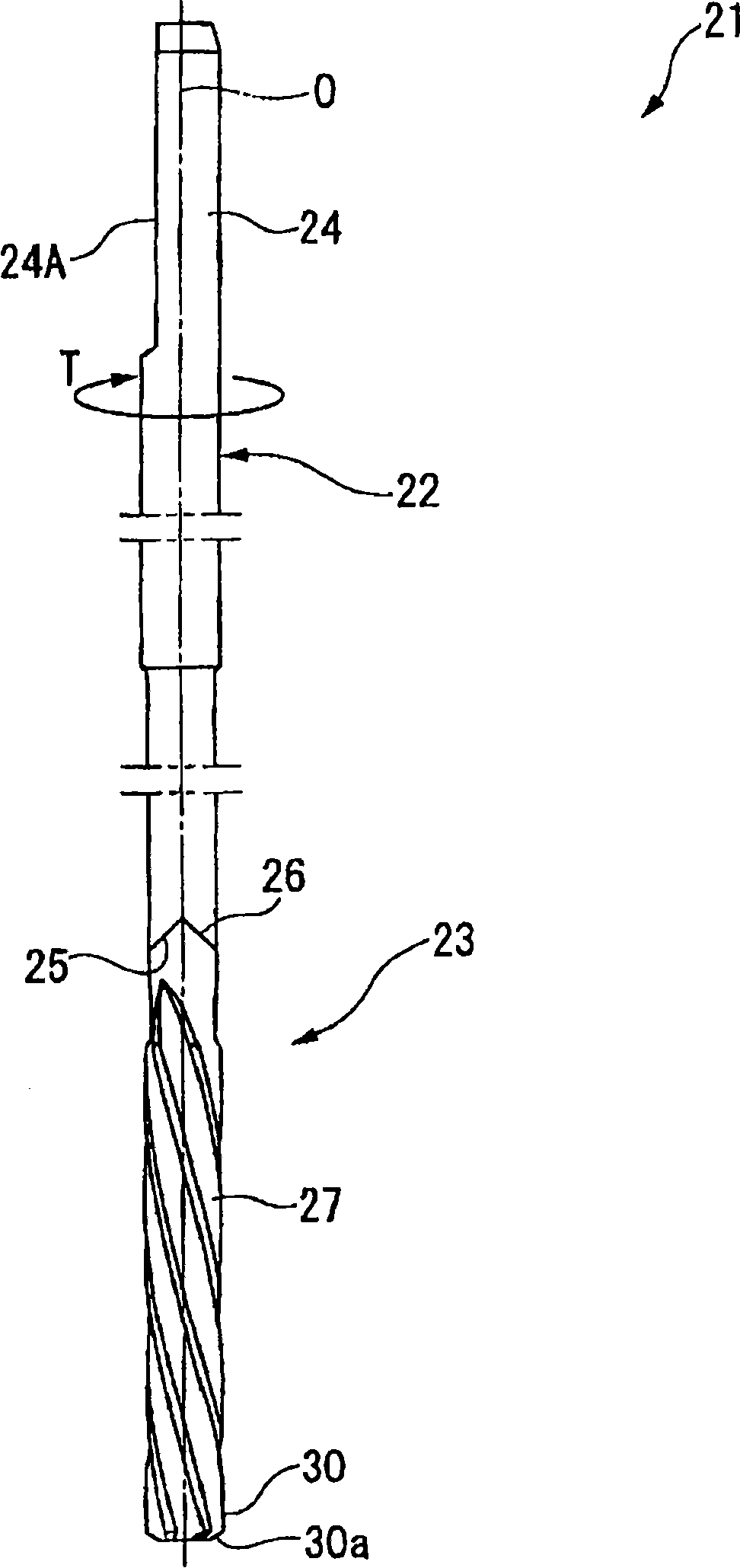
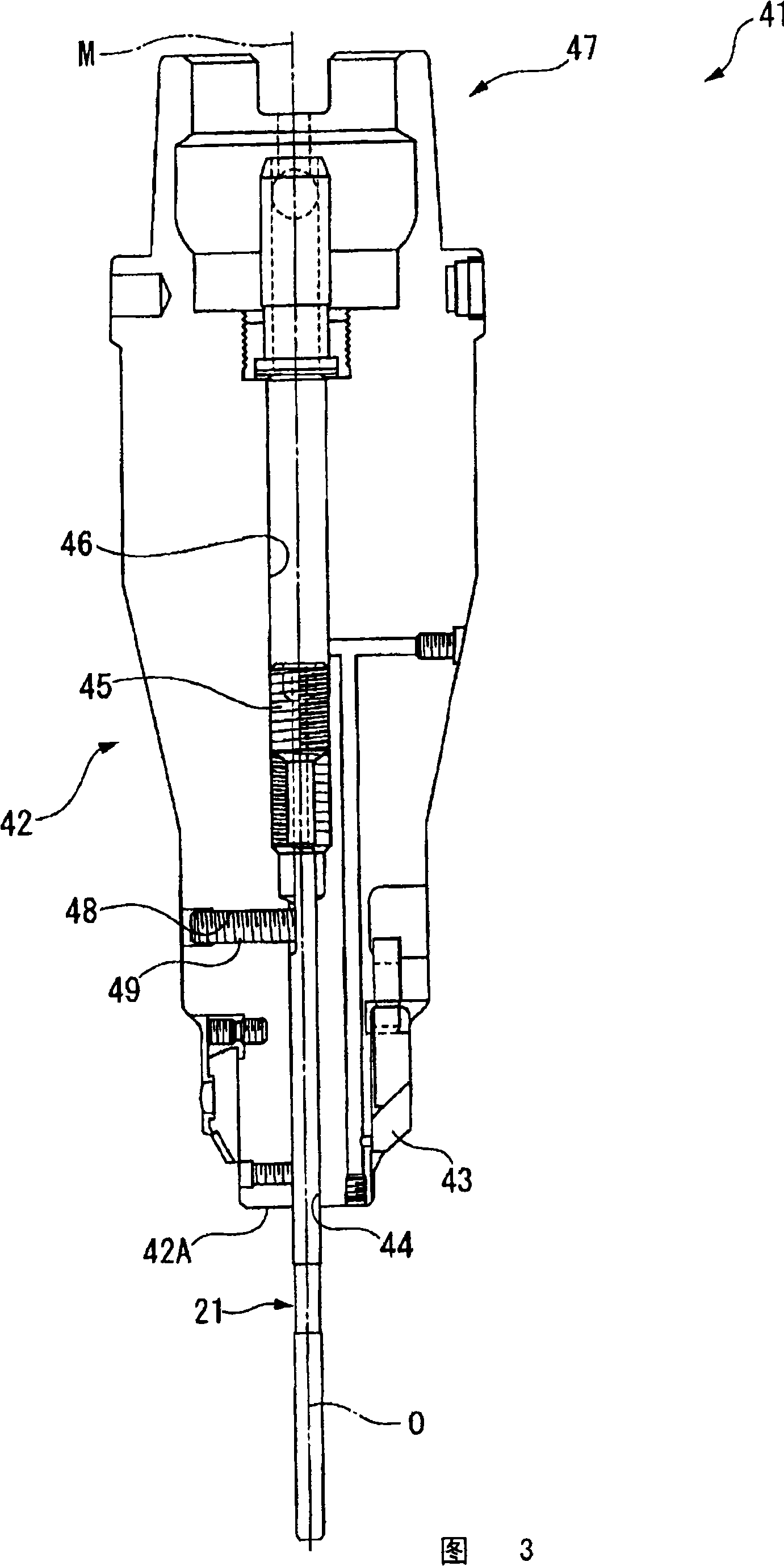
[0078] Next, a drilling tool as a first embodiment of the present invention will be described with reference to the drawings. exist figure 1 and figure 2 shows a reamer as a drilling tool according to an embodiment of the present invention. In addition, FIG. 3 shows a cutting tool to which this reamer is attached.

[0079] The hinge 21 consists of a long cylindrical shank 22 and a front end side of the shank 22 (in the figure 2 Middle is the lower side) of the knife edge portion 23 constitutes.

[0080] The shank 22 has a substantially multistage cylindrical shape centered on the axis O, and on the rear end side ( figure 2 The upper side in the middle) is provided with a mounting portion 24 for mounting the hinge 21 on the cutting tool 41 . The mounting portion 24 is provided with a flat surface 24A extending parallel to the axis O. As shown in FIG.

[0081] The diameter of the front end side of the shank 22 is one level smaller than that of the rear end side, and a ...


PUM


Abstract

A boring tool capable of accurately forming a bored hole by securing the rigidity of a reamer to prevent turnout of the reamer at high speeds and enabling an increase in life by suppressing the breakage thereof by cutting resistance. The boring tool (21) is inserted into a pilot hole formed in a workpiece beforehand to cut the inner wall surface of the pilot hole. The boring tool comprises a shank part rotated about an axis (O), an edge part with a cutting edge (30) at the tip of the shank part, and a chip discharging groove (27) formed in the outer peripheral part of the edge part and extending from the tip side to the rear end side. The cutting edge (30) is formed at a crossed ridge part between the wall surface (28) of the chip discharging grove (27) facing forward in the tool rotating direction (T) and the outer peripheral surface (29) of the edge part. The boring tool is characterized in that the cross-section of the chip discharging groove (27) vertical to the axis (O) is formed in a U-shape.

Description

technical field [0001] The present invention relates to a hole machining tool that is inserted into a pre-drilled hole formed in advance in a material to be cut to cut the inner wall surface of the pre-drilled hole, and a pre-drilled hole that uses the hole machining tool to form a machined hole with a predetermined inner diameter processing method. Background technique [0002] As such a drilling tool, for example, as described in Patent Document 1, there is known a reamer having a long cylindrical shank that rotates around an axis, and a tip portion formed on the front end side of the shank. A chip discharge groove extending toward the rear end side in the axial direction is formed on the outer peripheral portion of the tip portion, and a cutting edge is formed on a ridge line portion on the front end outer peripheral side of the wall surface of the chip discharge groove facing the front side in the tool rotation direction. [0003] This reamer is mounted on a cutting too...

Claims


Application Information

Patent Timeline
IPC IPC(8): B23D77/00
Inventor 泷口正治
Owner MITSUBISHI MATERIALS CORP
Why Eureka
Try Eureka