Sound-heat liquid magnetofluid AC generating system
A technology for a power generation system and an alternator, which is applied to electrical components, electromechanical devices, etc., can solve the problems of high cost of the magnetic fluid power generation system, high cost of the engine, complicated thermoacoustic engine, etc. The effect of small guide heat and low operating frequency
- Summary
- Abstract
- Description
- Claims
- Application Information
AI Technical Summary
Problems solved by technology
Method used
Image
Examples
Embodiment 1
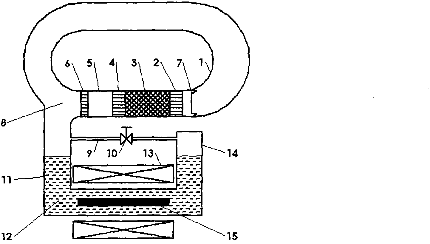
[0037] Such as figure 1 As shown, the thermoacoustic power generation system of this embodiment includes a traveling wave thermoacoustic engine and a liquid magnetic fluid generator. The working medium in the thermoacoustic engine is gas such as nitrogen, and the working medium in the liquid magnetic fluid engine is liquid magnetic fluid such as Gallium metal is liquid at room temperature. The traveling wave thermoacoustic engine includes a feedback tube 1 connected in sequence to form a traveling wave circuit, a heat exchanger 2 at the room temperature end, a regenerator 3, a heater 4, a thermal buffer tube 5, and a heat exchanger 6 at the room temperature end to eliminate The elastic membrane 7 of the loop direct current, the tee 8 and each annular connecting pipe; the liquid magnetic fluid generator is a liquid magnetic fluid alternator installed at the tee 8. When the heat enters the generator system from the heater 4, a temperature difference appears between the two end...
Embodiment 2
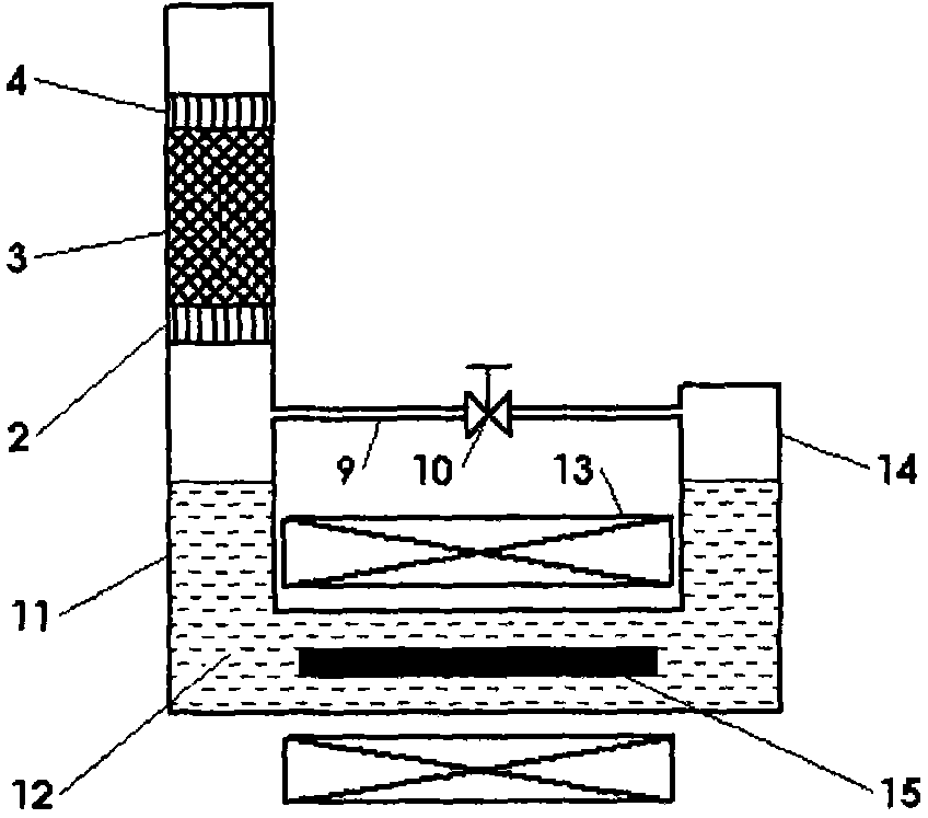
[0040] Such as figure 2 As shown, the thermoacoustic generator system in Embodiment 1 can also use a standing wave thermoacoustic engine to generate pressure fluctuations to drive liquid magnetic fluid movement; the standing wave thermoacoustic engine includes a heater 4, a plate stack 3, and a room temperature The end heat exchangers 2 are connected sequentially, and the plate stack 3 is functionally the same as the regenerator, and also produces a temperature gradient at both ends. When heat enters the engine system from the heater 4 , a temperature difference appears at both ends of the plate stack 3 , and a temperature gradient is established in the axial direction of the plate stack 3 . When the temperature gradient is greater than the critical temperature gradient, the standing wave thermoacoustic engine generates self-excited oscillations, converting thermal energy into mechanical energy, which is provided to the generator to drive the magnetic fluid movement to cut th...
Embodiment 3
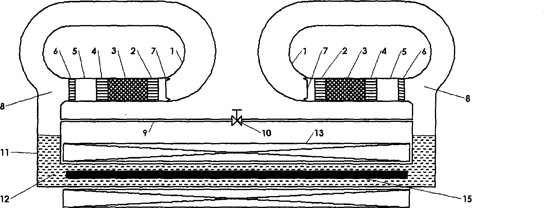
[0043] Such as image 3 As shown, on the basis of Embodiment 1, a row of wave-type thermoacoustic engines are respectively connected to both ends of the U-shaped electrically insulating flat pipe 11, thereby obtaining greater pressure fluctuations and increasing the movement speed of the magnetic fluid 12. , to improve the performance of the magnetic fluid generator. The structure and others of the traveling wave thermoacoustic engine are the same as those in Embodiment 1.
[0044] In this embodiment, a traveling-wave thermoacoustic engine in the form of a loop is used. Those skilled in the art can easily understand that a coaxial traveling-wave thermoacoustic engine or a standing-wave thermoacoustic engine may also be used. The structure of the coaxial traveling wave thermoacoustic engine can be the same as that of the coaxial traveling wave thermoacoustic engine in embodiment 1, and the structure of the standing wave thermoacoustic engine can be the same as that of embodime...
PUM
 Abstract
Description
Claims
Application Information
 - R&D
- Intellectual Property
- Life Sciences
- Materials
- Tech Scout
- Unparalleled Data Quality
- Higher Quality Content
- 60% Fewer Hallucinations
Browse by: Latest US Patents, China's latest patents, Technical Efficacy Thesaurus, Application Domain, Technology Topic, Popular Technical Reports.
© 2025 PatSnap. All rights reserved.Legal|Privacy policy|Modern Slavery Act Transparency Statement|Sitemap|About US| Contact US: help@patsnap.com


