
Cross current intrinsic cycle ultrasonic and microwave leaching reactor and leaching method thereof

A technology of ultrasonic wave and reactor, which is applied in the leaching of active ingredients in Chinese herbal medicine, and in the field of leaching reactors with cross-flow internal circulation of ultrasonic and microwave, which can solve the problems of ultrasonic and microwave equipment limitations, uneven effect, and reduced efficiency. , to achieve the effect of improving leaching and reaction efficiency, strengthening fluid flow, and preventing the formation of dead ends

Inactive Publication Date: 2008-10-01
INST OF PROCESS ENG CHINESE ACAD OF SCI +1
View PDF0 Cites 24 Cited by
  • Summary
  • Abstract
  • Description
  • Claims
  • Application Information

AI Technical Summary

Problems solved by technology

There are mainly four types of arrangement of ultrasonic vibrators, 1) cleaning ultrasonic equipment: the ultrasonic vibrator is installed at the bottom, which can be easily operated, but there is only one direction of ultrasonic field, the ultrasonic field is not uniform, and the mixing of materials is not uniform enough; The frequency of the ultrasonic vibrator is about 30khz, and the distance of energy transmission is about 300MM. The range of ultrasonic action is narrow, and the crushed Chinese herbal medicine is easy to precipitate, resulting in uneven ultrasonic emission. The relative range of action is reduced, reducing efficiency and affecting Enlarging the scale of production equipment
2) Central vibrator immersion ultrasonic: The ultrasonic vibrator is installed in the middle of the container, which increases the multi-directionality of the vibrator, and the uniformity of the applied solvent also increases, but when the energy of the vibrator increases to a certain extent, the vibrator The heat dissipated is very large, and the volume of the vibrator is small, making the effect uneven
Since the mixture may be repeatedly subjected to ultrasonic action, it will not reach a mixed solution with a high probability of action in a short time. If the material concentration is high, it will easily cause blockage of the material, and at the same time, the action volume is still not easy to enlarge.
4) Peripheral vibrator: Several high-power ultrasonic vibrators are installed on the outer wall of the reactor, the ultrasonic field is uneven, and the effect of ultrasonic waves is uneven
[0003] Most of the above-mentioned equipment uses square and tank-shaped cleaning equipment. The ultrasonic and microwave vibrators are located at the bottom of the cleaning tank. Due to this structure, the operating distance of ultrasonic and microwave is limited, so ultrasonic and microwave equipment are limited in the amplification process.
For some ultrasonic and microwave leaching reactions, the air-lift circulation ultrasonic crushing device is used. The ultrasonic probe is located in the center of the guide tube. Although the strength of this probe is very large, the strength is limited. During the entire ultrasonic amplification process, The power of ultrasonic emission is limited, so the amplification of the whole extraction device is also limited
Some devices with ultrasonic generators installed in the shell cannot make the volume of the whole tank large, because the effective distance of ultrasonic waves is limited, which limits the amplification of ultrasonic equipment in the process of industrialization

Method used


Image

  • Cross current intrinsic cycle ultrasonic and microwave leaching reactor and leaching method thereof
  • Cross current intrinsic cycle ultrasonic and microwave leaching reactor and leaching method thereof
  • Cross current intrinsic cycle ultrasonic and microwave leaching reactor and leaching method thereof

Examples


Embodiment 1

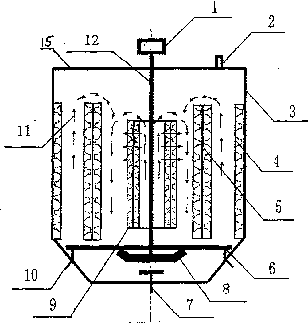
[0053] refer to Figure 1a and Figure 1b , to make a cross-flow internal circulation ultrasonic and microwave leaching reactor with three layers of ultrasonic vibrator rings, the reactor shell 3 is made of stainless steel into a cylinder with a height of 3500mm×diameter of 1500mm, and the bottom of the cylinder is trapezoidal The housing 3, the upper cover 15 of stainless steel is installed on the upper mouth of the reactor housing 3, and the upper cover 15 is provided with an air outlet 2 for adjusting the pressure in the tank; the shaft 12 of the agitator 1 and the shaft 12 are installed The stirring blade 8 passes through the upper cover 15 and is sealed and installed in the center of the reactor shell 3 .

[0054] The first layer of ultrasonic vibrator group ring 9 is composed of four vibrator boxes 16 arranged at equal intervals along the outer wall of the first layer of cylinder 13 and installed on the outer wall. The distance between the vibrator boxes 16 is 100mm. Th...

Embodiment 2

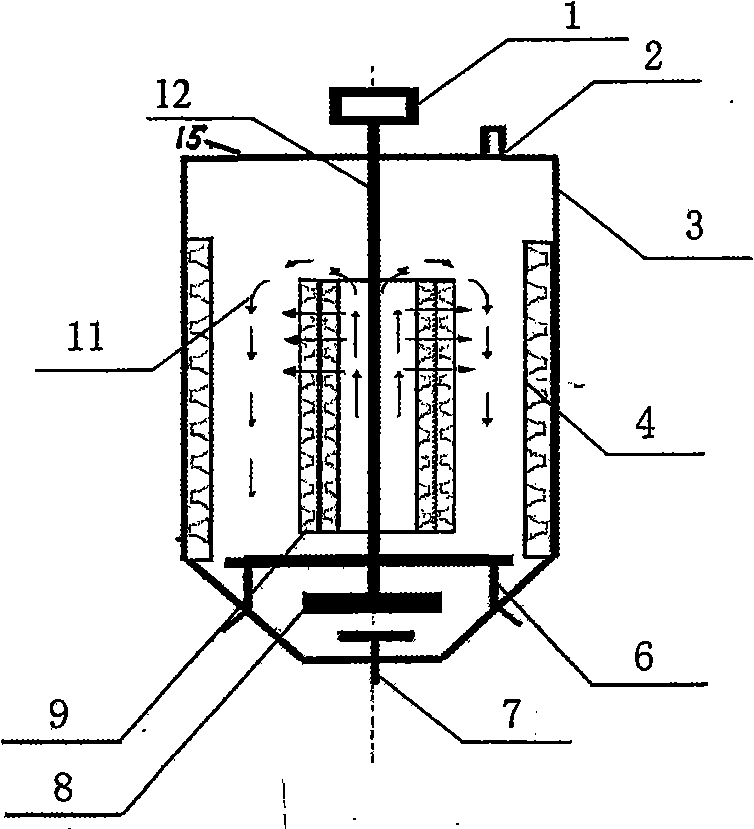
[0062] Referring to Figure 2, a cross-flow internal circulation ultrasonic and microwave leaching reactor with two layers of ultrasonic vibrator rings is produced. The reactor is made of stainless steel into a shell 3 with a height of 2500mm×diameter of 1200mm, and the bottom of the shell 3 is The upper cover 15 made of trapezoidal and cylindrical stainless steel material is installed on the shell 3 of the reaction kettle; the upper cover 15 is provided with an air outlet 2 for adjusting the pressure in the tank; The upper stirring blade 8 passes through the upper cover 15 and is sealed and installed in the center of the reactor shell 3 .

[0063] The first layer of ultrasonic vibrator ring 9 is composed of 4 vibrator boxes arranged in a circle. 11 transducer vibrators of the same size are installed in a vibrator box, each vibrator has a diameter of 50mm and a thickness of 50mm, and is arranged in a staggered manner at equal intervals. There are 2 transducers in the first row,...

Embodiment 3

[0068] exist Figure 1a and Figure 1b ,or Figure 2a and Figure 2b In the equipment, apply the method of the present invention to carry out the leaching of Liquiritigenin in Radix Glycyrrhizae, and its concrete processing step is as follows:

[0069] 1). Grinding medicinal licorice into 5-100 mesh granular grass powder;

[0070] 2). The grass powder crushed in step 1) is weighed according to the ratio of grass powder to water of 1 g: 20 liters; first put the liquid into the cross-flow internal circulation ultrasonic and microwave leaching reaction of Example 1 Put the solid powder into the kettle. Firstly, when the liquid feed liquid is fed, the aeration and stirring will be started. The gas introduced is air, and its flow rate is 1 / 10 of the volume. When the solid feed is fed, the mechanical agitation is turned on. Wherein the stirring speed is 60 rev / min;

[0071] 3). After the liquid and solid in step 2) are fully mixed, turn on the ultrasonic wave, and the ultrasonic...


PUM


Abstract

The invention relates to a dipping reaction kettle and a dipping method used for cross-flow internal circulation ultrasonic and microwave. The dipping reaction kettle comprises a reaction kettle shell, an upper cover with a ventilation hole, an ultrasonic vibrator group, a mixer, a first cylinder, a first layer of ventilation ring, a second layer of ventilation ring and a third layer of ventilation ring, wherein, the upper cover is arranged on the upper mouth of the reaction kettle shell; the mixer is arranged in the reaction kettle shell; the first cylinder is arranged in the reaction kettle shell; the first layer of ultrasonic vibrator group is arranged around the first cylinder; the third layer of ultrasonic vibrator group is arranged around the internal wall of the reaction kettle shell; the first layer of ventilation ring is arranged at the bottom inside the reaction kettle shell; the second layer of ventilation ring is arranged in the reaction kettle shell and between the first layer of ultrasonic vibrator group ring and the third layer of the ultrasonic vibrator group ring; an external power supply is respectively and electrically connected with a mixing motor, the first layer of ultrasonic vibrator group ring, the second layer of ultrasonic vibrator group ring and the third layer of the ultrasonic vibrator ring. The device of the invention can be used for extracting the active components in Chinese herbal medicine.

Description

technical field [0001] The invention relates to a cross-flow leaching reaction kettle, in particular to a cross-flow internal circulation ultrasonic and microwave leaching reaction kettle, and a method suitable for leaching active ingredients in Chinese herbal medicines. Background technique [0002] The methods currently used in the extraction of Chinese herbal medicines are mainly high temperature and high pressure leaching, solvent extraction, supercritical extraction, etc. These methods have problems such as long operation time, high impurity content, and low extraction rate. Utilizing ultrasonic leaching of Chinese herbal medicine is a new technology for extracting Chinese herbal medicine. It has made great progress in the extraction of volatile spices Rosmarinus officinalis, perishable substances in garlic, and hops. Ultrasonic waves can form high-pressure cavity blasting, vibration and chemical reactions around plant particles leached by solvents, improving extraction...

Claims


Application Information

Patent Timeline
Patent Type & Authority Applications(China)
IPC IPC(8): B01D11/02B01J19/10
Inventor 查丽杭苏志国王德增
Owner INST OF PROCESS ENG CHINESE ACAD OF SCI
Learn More