
High phosphorous poisoning resistant catalysts for treating automobile exhaust

一种催化剂、耐受性的技术,应用在物理/化学过程催化剂、催化剂活化/制备、排气处理等方向,能够解决被污染等问题

Active Publication Date: 2008-09-10
BASF CATALYSTS LLC
View PDF13 Cites 5 Cited by
  • Summary
  • Abstract
  • Description
  • Claims
  • Application Information

AI Technical Summary

Problems solved by technology

However, such systems are ineffective at the level of protection achieved, can become quickly polluted, and can remove needed antioxidants from the oil

Method used


Image

  • High phosphorous poisoning resistant catalysts for treating automobile exhaust
  • High phosphorous poisoning resistant catalysts for treating automobile exhaust

Examples


Embodiment

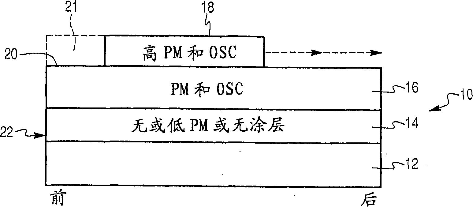
[0047] In this embodiment, form as figure 1 Catalysts shown.

[0048] The first poison trap layer is formed on the ceramic honeycomb. 92.8 parts of gamma-alumina were combined with 7.3 parts of alumina-based binder, 2.9 parts of zirconia-based binder, 562 parts of deionized water, and 70 parts of 90% concentrated acetic acid prior to milling to produce 40% solids Slurry. Milling was performed until the particle size distribution showed that 90% of the particles became smaller than 10 microns.

[0049] After milling, the slurry was coated on a ceramic honeycomb with 900 cells per square foot (cpsi) and 2.5 mil wall thickness. Coating was performed by immersing the honeycomb substrate in the slurry, dripping the slurry dry, and then blowing off the excess slurry with compressed air. The coated honeycomb was dried at 110°C for 4 hours and calcined at 550°C for 2 hours.

[0050] The intermediate layer is then formed through the following steps. In a planetary mixer, 0.9 part...


PUM


Abstract

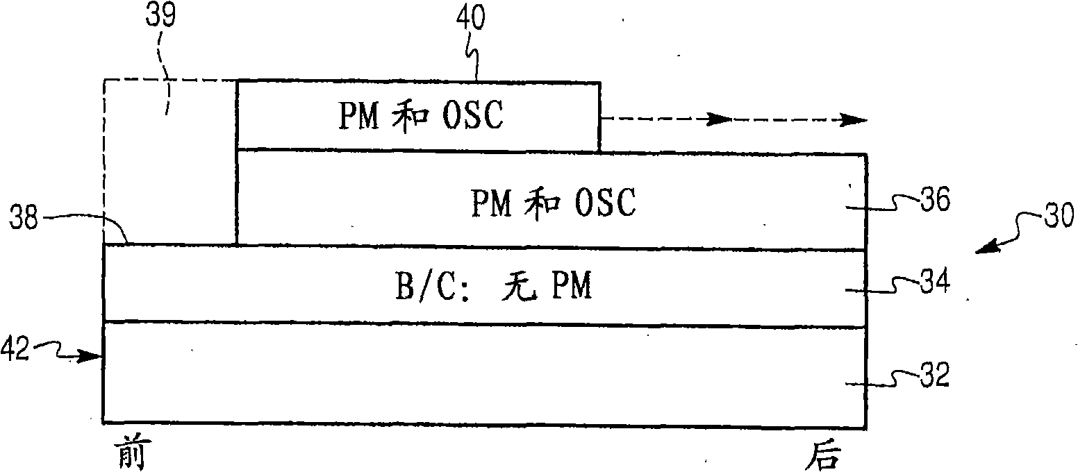
The present invention discloses novel catalysts for treating automobile exhaust that have increased resistance to poisoning from oil- and / or fuel-derived additives, hi the catalysts of this invention, the catalytic materials are not coated onto a front-end poison capture zone of the support that carries the catalytic layers. Since poisonous elements tend to deposit on the upstream end of the catalyst, such poisons do not inactivate any of the catalytic materials.

Description

technical field [0001] The present invention generally relates to a system for minimizing the deleterious effects of oil-derived and / or gasoline-added compounds on an automotive exhaust aftertreatment system. Background of the invention [0002] Automotive exhaust control is a mature industry. The US Clean Air Act of 1965 and subsequent regulations in other countries required automakers and suppliers to control and reduce vehicle tailpipe emissions. Since the periodic lowering of the tailpipe restriction has been made possible by the use of catalytic converters, the base engine exhaust of controlled exhaust products has been greatly reduced over the past three decades. [0003] Catalytic converters generally contain one or more reducing hydrocarbons (HC), carbon monoxide (CO) and / or nitrogen oxides (NO x ) as catalytic elements. Some catalytic systems are also designed to reduce particulate matter in diesel engines. [0004] Individual catalysts can be coated on ceramic ...

Claims


Application Information

Patent Timeline
Patent Type & Authority Applications(China)
IPC IPC(8): B01J35/04B01J23/40B01D53/94F01N3/08
CPCF01N3/085F01N2510/0682Y02T10/22F01N2370/02F01N2510/06B01D53/945B01J35/0006B01J35/04B01J23/63F01N3/0828F01N3/0814Y02C20/10B01J37/0244B01D2255/1023B01D2255/1025B01D2255/204B01D2255/9025B01D2258/014Y02A50/20B01J35/19B01J35/56B01J23/38B01D53/34F01N3/10Y02T10/12
Inventor S·F·陈
Owner BASF CATALYSTS LLC
Learn More