
On-off synchronous control rail-hanging type brake

A start-stop synchronization and synchronous control technology, which is applied in the direction of brake types, brake components, brake actuators, etc., can solve the problems of increased acceleration of transportation equipment, injury to people, and insufficient smooth braking, so as to reduce the occurrence rate, Easy installation and layout, simple structure

Inactive Publication Date: 2010-04-21
TAIYUAN UNIV OF TECH
View PDF5 Cites 0 Cited by
  • Summary
  • Abstract
  • Description
  • Claims
  • Application Information

AI Technical Summary

Problems solved by technology

The mechanical suspension rail brake has a huge structure. Although the braking torque is relatively large, the braking process is relatively short, and it is easy to generate a large impact, resulting in unstable braking and accidents.
Although the braking process of the hydraulic hanging rail brake is more stable than that of the mechanical type, it can realize stepless speed regulation during the braking process, but there are many kinds of hydraulic components in the hydraulic system, which makes the hydraulic system too complicated and the operation is cumbersome. At the same time, the hydraulic braking system adopts The open system is easily affected by the surrounding environment. After the oil is polluted, the entire system (especially important valves) often fails to work normally
Neither of these two methods can achieve start-stop synchronization. At present, during the working process of many transportation equipment, especially in downhill conditions, the sliding force generated by the gravity of the material greatly exceeds the running resistance. When parking and braking, The sliding force all acts on the braking device, resulting in a sudden increase in the acceleration of the transportation equipment, which may easily lead to the failure of the braking device and cause speeding, causing injuries and other accidents

Method used


Image

  • On-off synchronous control rail-hanging type brake
  • On-off synchronous control rail-hanging type brake
  • On-off synchronous control rail-hanging type brake

Examples


Embodiment Construction

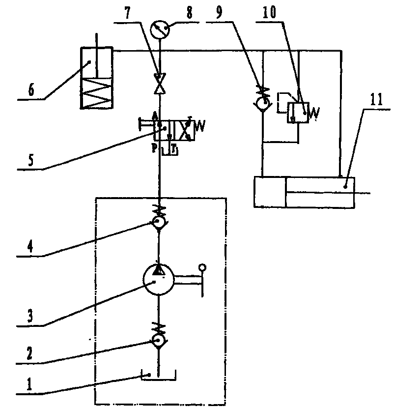
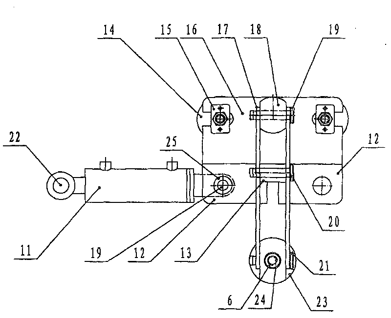
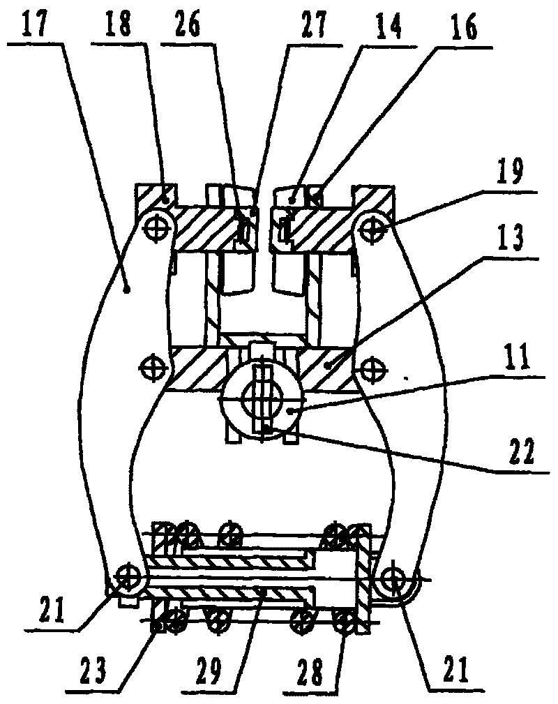
[0013] The roller 36 rotates around the support shaft 31 under the cooperation of the bearing 30, and the bearing end cover 34 is pressed on the bearing 30 under the cooperation of the circlip 35. There are two circular holes on the limit plate 15, and the limit plate 15 The function is to locate the support shaft 31 on the support frame 16 with the conical pin 33. The support frame 16 is a "U" type weldment, and two groups of earring connecting plates 12 are welded at the bottom of the supporting frame 16. The earring connecting plates 12 The effect is to connect double-acting oil cylinder 11, double-acting oil cylinder 11 is connected on the earring connecting plate 12 with pin 19, welded a square rigid body 13 for connecting drive plate 17 in the middle of two groups of earring connecting plates 12.

[0014] First, the oil inlet and outlet of the hand pump 3 are connected to the check valves 2 and 4 respectively, and the oil inlet of the reversing valve 5 is connected to the...


PUM


Abstract

A start-stop synchronization control hanging rail type arrester used for braking system of rail type transport equipment is provided, which has simple structure, easy operation and start-stop synchronization control function. The present invention comprises a synchronization control mechanism and a hydraulic pressure locking mechanism; the synchronization control mechanism comprises a manual pump,a reversing valve, a stop valve, a check valve, a relief valve, a single directional hydraulic cylinder and a double-acting cylinder; the oil inlet and outlet ports of the single directional hydrauliccylinder are connected with the stop valve and cavity of pole of the double-acting cylinder, the oil inlet port of the stop valve is connected with manual pump; the hydraulic pressure locking mechani sm comprises a dangler connection board, a support rack, a square rigid body, a pin, a driver plate, a transmission shaft, a friction block, a spring, a spring baffle, a support axes, a nut, a location-limited plate, an idler wheel and a bearing; the dangler of cavity of pole of double-acting cylinder is connected with dangler connection board by pin; the square rigid body is connected driver plate by pin, the driver board is connected with the transmission shaft by pin, the friction block is arranged on transmission shaft by taper pin.

Description

technical field [0001] The invention relates to a start-stop synchronous suspension rail type safety brake protection device. Background technique [0002] Existing suspension rail brake adopts two kinds of modes mostly, mechanical type suspension rail brake and hydraulic type suspension rail brake. The mechanical suspension rail brake has a huge structure. Although the braking torque is large, the braking process is relatively short, and it is easy to generate a large impact, resulting in insufficient braking stability and accidents. Although the braking process of the hydraulic suspension rail brake is more stable than that of the mechanical type, it can realize stepless speed regulation during the braking process, but there are many kinds of hydraulic components in the hydraulic system, which makes the hydraulic system too complicated and the operation is cumbersome. At the same time, the hydraulic braking system adopts The open system is easily affected by the surroundi...

Claims


Application Information

Patent Timeline
Patent Type & Authority Patents(China)
IPC IPC(8): F16D65/24F16D65/095F16D65/22
Inventor 寇子明吴娟卫进张延军寇保福李奇张静王晓飞
Owner TAIYUAN UNIV OF TECH
Learn More