Battery control circuit, battery control method and battery
A battery control and circuit technology, applied in circuits, battery pack components, secondary battery repair/maintenance, etc., can solve problems such as low safety, gas production, expansion, etc., to ensure normal flow, avoid temperature surges, The effect of ensuring the overall safety performance
- Summary
- Abstract
- Description
- Claims
- Application Information
AI Technical Summary
Problems solved by technology
Method used
Image
Examples
Embodiment 1
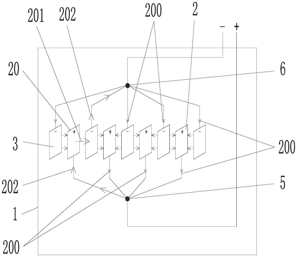
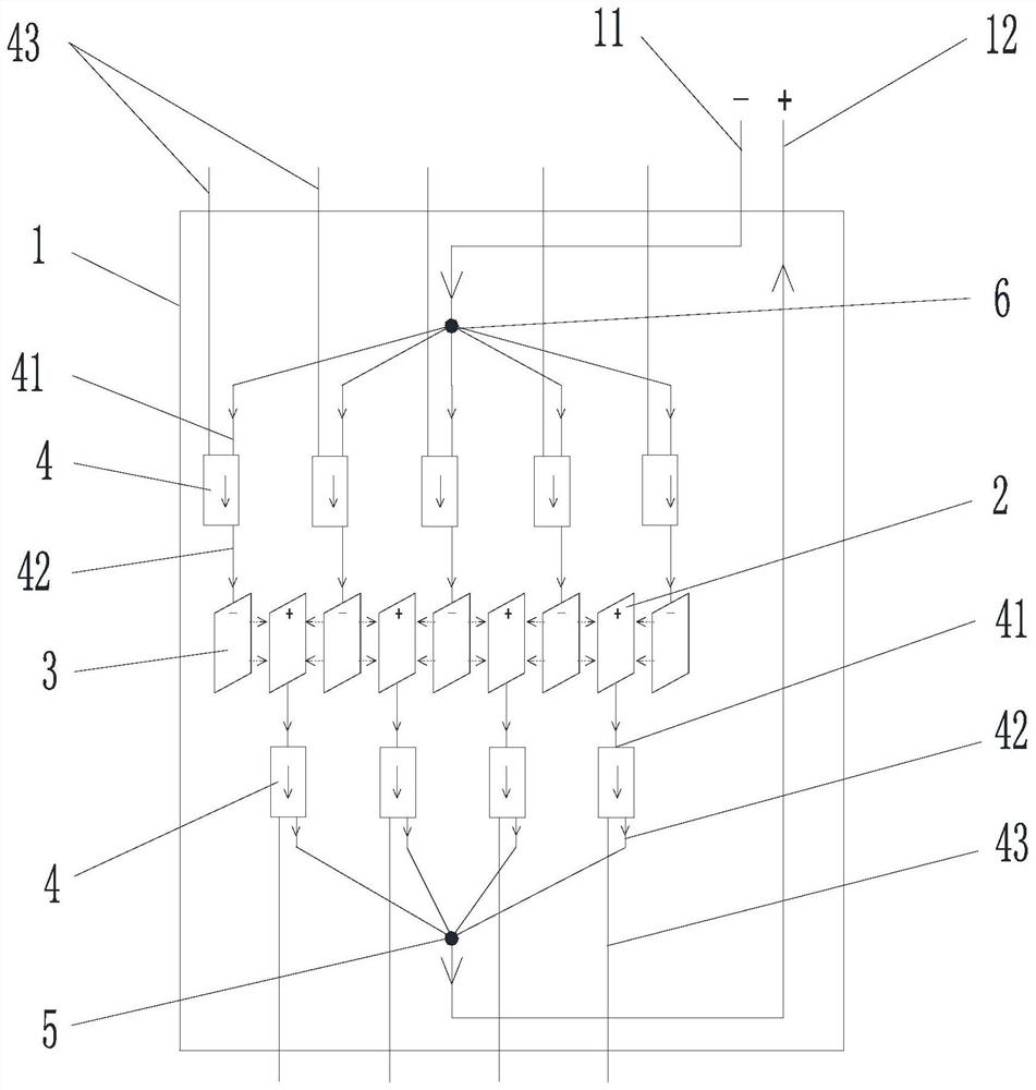
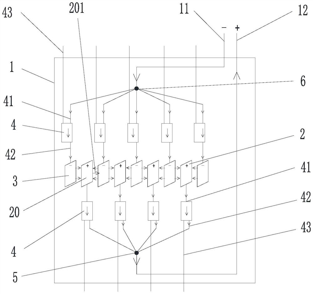
[0041] Such as Figure 2 to Figure 4 As shown, a battery control circuit in this embodiment is arranged in the battery body 1, and the battery body includes a plurality of positive electrode sheets 2 and a plurality of negative electrode sheets 3, and any one of the positive electrode sheets 2 and the positive electrode connection terminal 5 of the battery body A unidirectional conduction module 4 is arranged between any negative electrode sheet and the negative terminal 6 of the battery body, and the unidirectional conduction module 4 includes a first end 41 for current input or output, and a first terminal 41 for current output or The second terminal 42 for input and the control terminal 43 for switching the current direction. Further, the one-way conduction module 4 in this embodiment also includes a first electric control assembly 7 and a second electric control assembly 8 connected in parallel, and the first and second electric control assemblies are used to turn on and s...
Embodiment 2
[0048] Such as Figure 5 As shown, this embodiment is based on the first embodiment. As a preferred implementation mode, the first electronic control component 7 in this embodiment is the first triode 71, and the second electronic control component 8 is the first triode 71. The second and third transistors 81, the bases of the first and second transistors are connected to the control terminal, so as to play the role of controlling the input control signal.
[0049] It should be noted that the one-way conduction module in this embodiment is composed of the collectors and emitters of two triodes of the same type connected in reverse, and the two reverse contacts are respectively connected to the current input / output line and the electrode of the collector. The bases of the two triodes are respectively connected to the control terminals of the one-way conduction module (the control terminals in this embodiment include the first control terminal and the second control terminal). ...
Embodiment 3
[0052] Such as Figure 6 As shown, this embodiment is based on the first embodiment. As a preferred implementation mode, the first electric control assembly 7 in this embodiment includes a first relay 72 and a first diode 73. The first The relay 72 and the first diode 73 are connected in series; the second electric control assembly 8 includes a second relay 82 and a second diode 83, and the second relay 82 and the second diode 83 are connected in series connect. Wherein, the first and second relays are connected to the control terminal.
[0053] It should be noted that the first and second relays and the first and second diodes in this embodiment are low-voltage circuit breakers and diodes commonly used in the prior art, so they will not be described in detail here.
PUM
 Abstract
Description
Claims
Application Information
 - R&D
- Intellectual Property
- Life Sciences
- Materials
- Tech Scout
- Unparalleled Data Quality
- Higher Quality Content
- 60% Fewer Hallucinations
Browse by: Latest US Patents, China's latest patents, Technical Efficacy Thesaurus, Application Domain, Technology Topic, Popular Technical Reports.
© 2025 PatSnap. All rights reserved.Legal|Privacy policy|Modern Slavery Act Transparency Statement|Sitemap|About US| Contact US: help@patsnap.com


