Inline type electric machine iron core and manufacturing method thereof

A manufacturing method and in-line technology, applied in the field of motor iron core, can solve complex and high-level equipment problems, achieve the effects of reducing difficulty, smooth bonding, and saving investment costs

Inactive Publication Date: 2008-07-23
NINGBO POLARIS TECH
View PDF2 Cites 14 Cited by
  • Summary
  • Abstract
  • Description
  • Claims
  • Application Information

AI Technical Summary

Problems solved by technology

Although the laminated iron core of the patent can reduce the winding and stacking time, the process of automatic winding during the winding forming process is more complicated than the traditional process of stamping laminations and then winding, and the requirements for equipment are also high. Therefore, in order to use the commonly used stamping core processing equipment and realize efficient mechanized winding, it is necessary to design a more optimized core structure and corresponding processing technology

Method used


Image

  • Inline type electric machine iron core and manufacturing method thereof
  • Inline type electric machine iron core and manufacturing method thereof
  • Inline type electric machine iron core and manufacturing method thereof

Examples


Embodiment Construction

[0027] The present invention will be further described in detail below in conjunction with the accompanying drawings and embodiments.

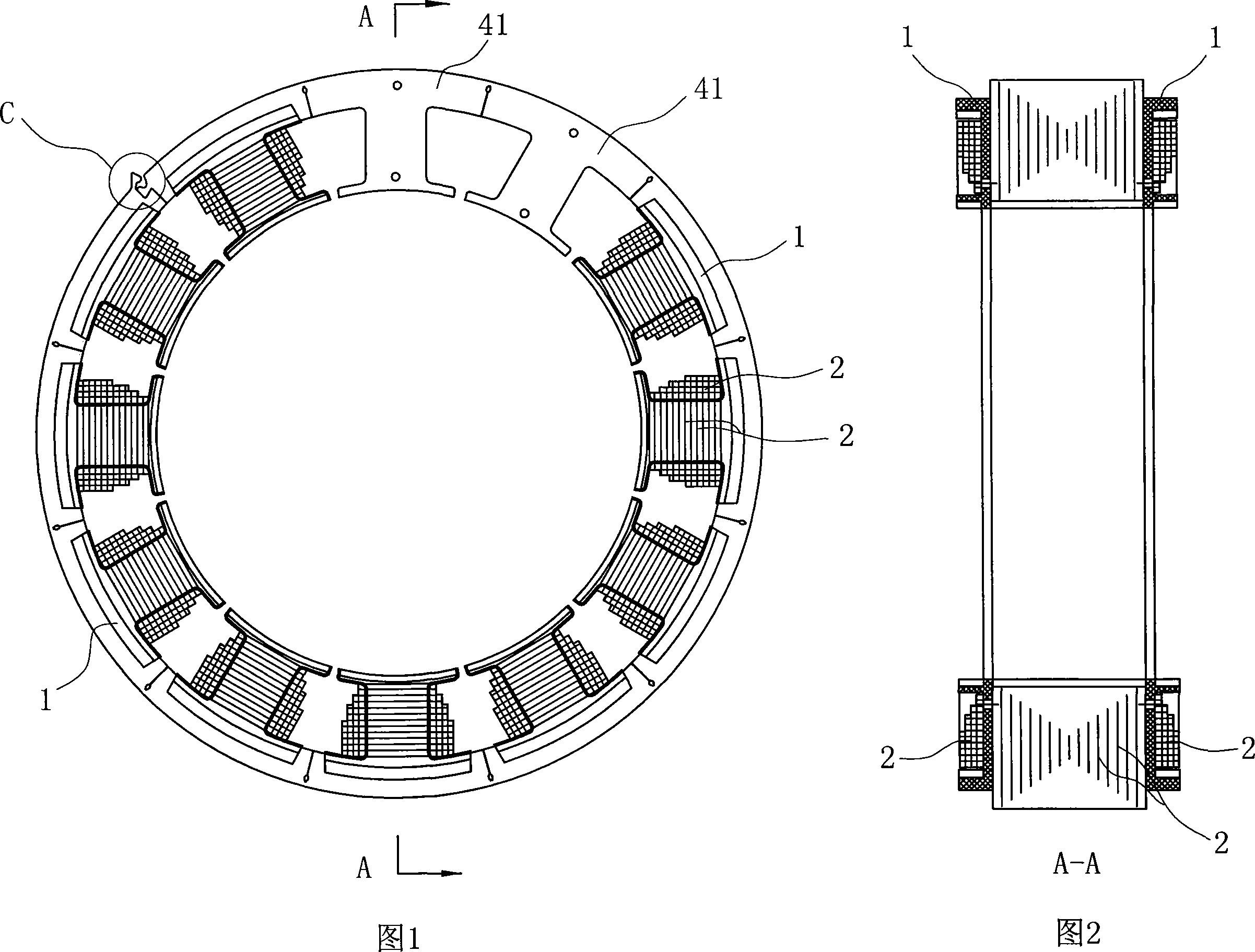
[0028] As shown in Figure 1 and Figure 2, it is a schematic diagram of the winding structure of the in-line motor iron core of the present invention. The insulator 1 is covered, and the coil 2 is wound on the insulator 1. The iron core has an interface, and the interface C is fixedly connected through a buckle structure.

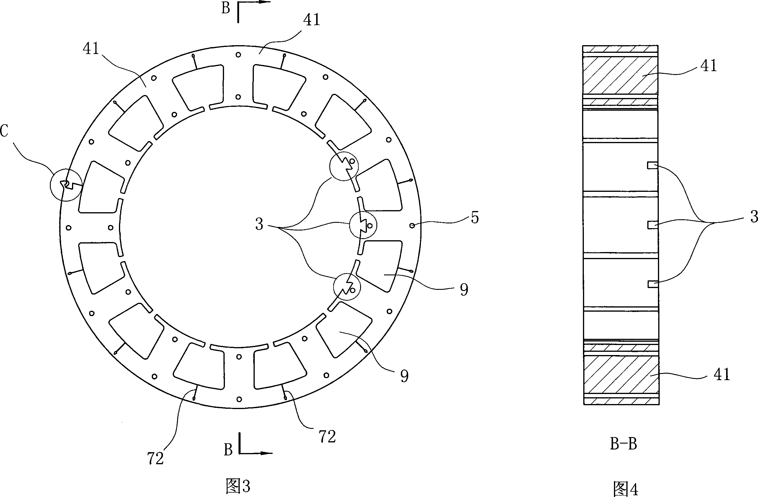
[0029] Figure 3 and Figure 4 are structural schematic diagrams of laminated iron core punches after removing the insulator 1 and coil 2 corresponding to Figure 1 and Figure 2, and three adjacent ones that can accommodate Hall slot 3 of the Hall element;

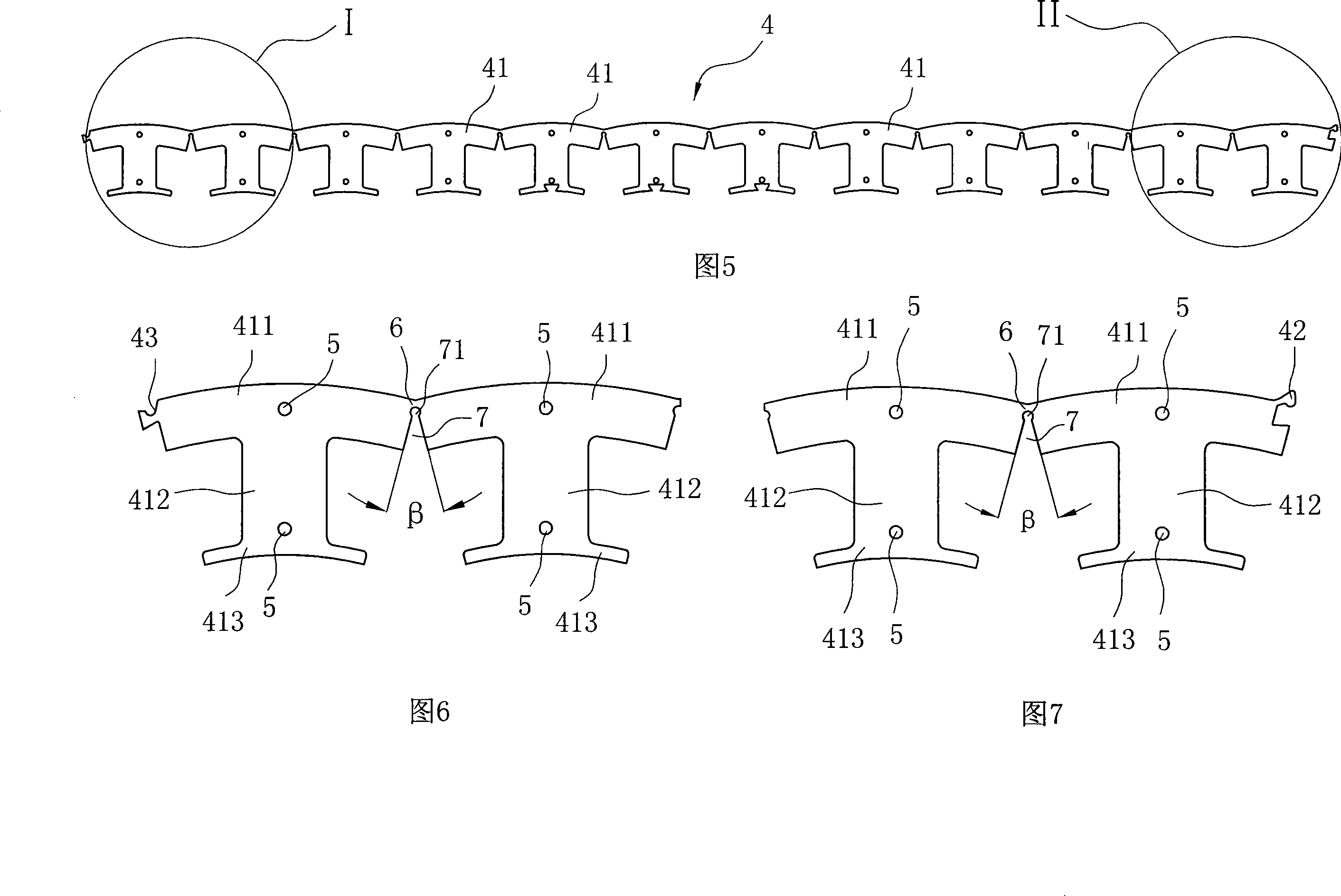
[0030] As shown in Figure 5, each of the circular iron core punches is wound from the in-line strip punches 4 in Figure 5, and each strip punch 4 includes 12 interconnected , an arc-shaped unit tooth block 41 in the shape of "I", the arc-shaped unit tooth block 41 include...


PUM

PropertyMeasurementUnit
Radial widthaaaaaaaaaa

Abstract

An inline motor iron core comprises a plurality of iron core punching sheets which are mutually pressed and stacked and take circular shape, which is characterized in that the iron core punching sheet is formed through coiling an inline strip-shaped punching sheet, each strip-shaped punching sheet comprises a plurality of arc unit tooth blocks which are mutually connected, two adjacent arc unit tooth blocks are connected with each other through a connecting portion which is bent under the exogenic action and is arranged on the outer rim direction, the lower portion of the connecting portion is opened, the opening is opened with an inner groove mouth on the closed angle portion, and head and tail arc unit tooth blocks on the same strip-shaped punching sheet are respectively provided with a buckle head and a clipping mouth which are mutually matched. The invention designs non-molding iron core punching sheets into inline strip-shaped punching sheets, which can greatly increase material utilization when in punching, an inner groove mouth is added on the connecting portion of the arc unit tooth block, which reduces stress between the adjacent arc unit tooth blocks which is caused by curling to shape, and ensures more stable and firmer attachment between the arc unit tooth sheets which are curled.

Description

technical field [0001] The invention relates to a motor core, in particular to a motor core structure capable of realizing mechanized winding and a processing method thereof. The motor core can be used not only as an outer stator core of a motor, but also as a rotor core of a generator . Background technique [0002] After the traditional iron core is designed and shaped, the stamping die is made according to the shape, and then the sheets are punched and stacked to form. At present, such a process is used for the common stator core as the inner rotor, so the material utilization rate is relatively low, generally within 50%. It is difficult to realize mechanized operation for winding, because the winding space of the formed iron core is very small, and the notch is also small. Even if mechanized operation is adopted, the winding efficiency is low. [0003] Therefore, in industrial applications, people have adopted another process method, which is to use a single strip mate...

Claims


Application Information

Patent Timeline
IPC IPC(8): H02K1/06H02K15/02
Inventor 晁会岩罗大铖
Owner NINGBO POLARIS TECH
Why Eureka
Try Eureka