Automatic temperature control cabinet

A technology of temperature control and temperature control device, which is applied in the direction of temperature control, non-electric variable control, control/regulation system, etc. It can solve the problem of not being able to reach the industrial level and working for a long time under the set conditions, it is difficult to measure internal temperature parameters, The surrounding environment has high requirements and other issues, and achieves the effect of colorful appearance, beautiful shape and good maintainability

Inactive Publication Date: 2008-07-16
SHANGHAI EVOC INTELLIGENT TECH
View PDF0 Cites 6 Cited by
  • Summary
  • Abstract
  • Description
  • Claims
  • Application Information

AI Technical Summary

Problems solved by technology

[0003] At present, the chassis commonly used in industry and commerce rely on the materials of the chassis itself and the chassis fan to realize the heat dissipation of the chassis; the chassis is clumsy, the fan is easy to age, and it is very easy to cause a crash and fail to work in a strong electromagnetic and relatively harsh environment.
Especially the operation at high temperature and low temperature, as well as temperature and electromagnetic interference, all of which limit the use range and occasions of the chassis, which makes the contradiction between the application range and demand of the electronic circuit more prominent
At the same time, the existing industrial and commercial conventional chassis are not only bulky, but also susceptible to interference and controlled by climate conditions. Most of them have fans, so the sealing is not good, and it is not easy to measure internal temperature parameters. Defects such as poor anti-electromagnetic interference, no temperature display, and high requirements for the surrounding environment
[0004] Therefore, for general chassis, it is difficult to operate in some harsh environments, and it is impossible to achieve industrial grade and work for a long time under the set conditions

Method used


Image

  • Automatic temperature control cabinet
  • Automatic temperature control cabinet
  • Automatic temperature control cabinet

Examples


Embodiment Construction

[0020] In order to understand the technical content of the present invention more clearly, the following examples are given in detail.

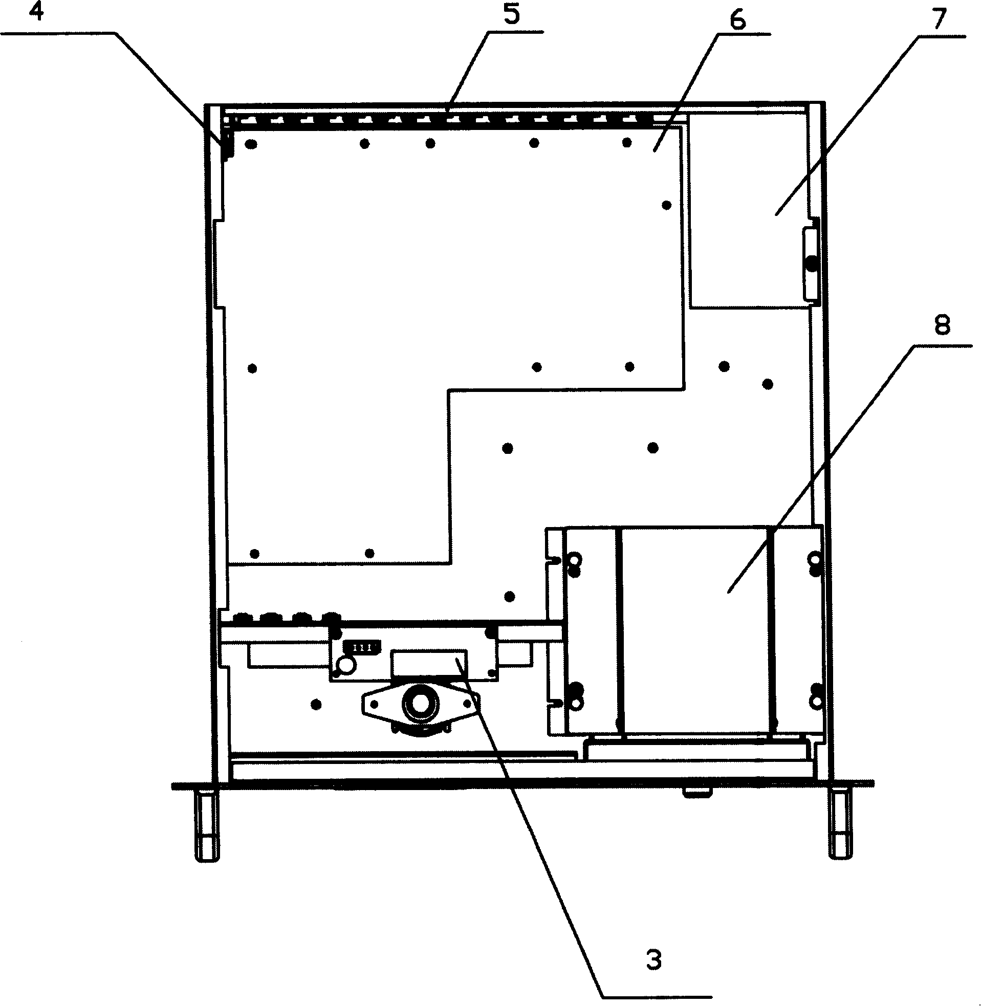
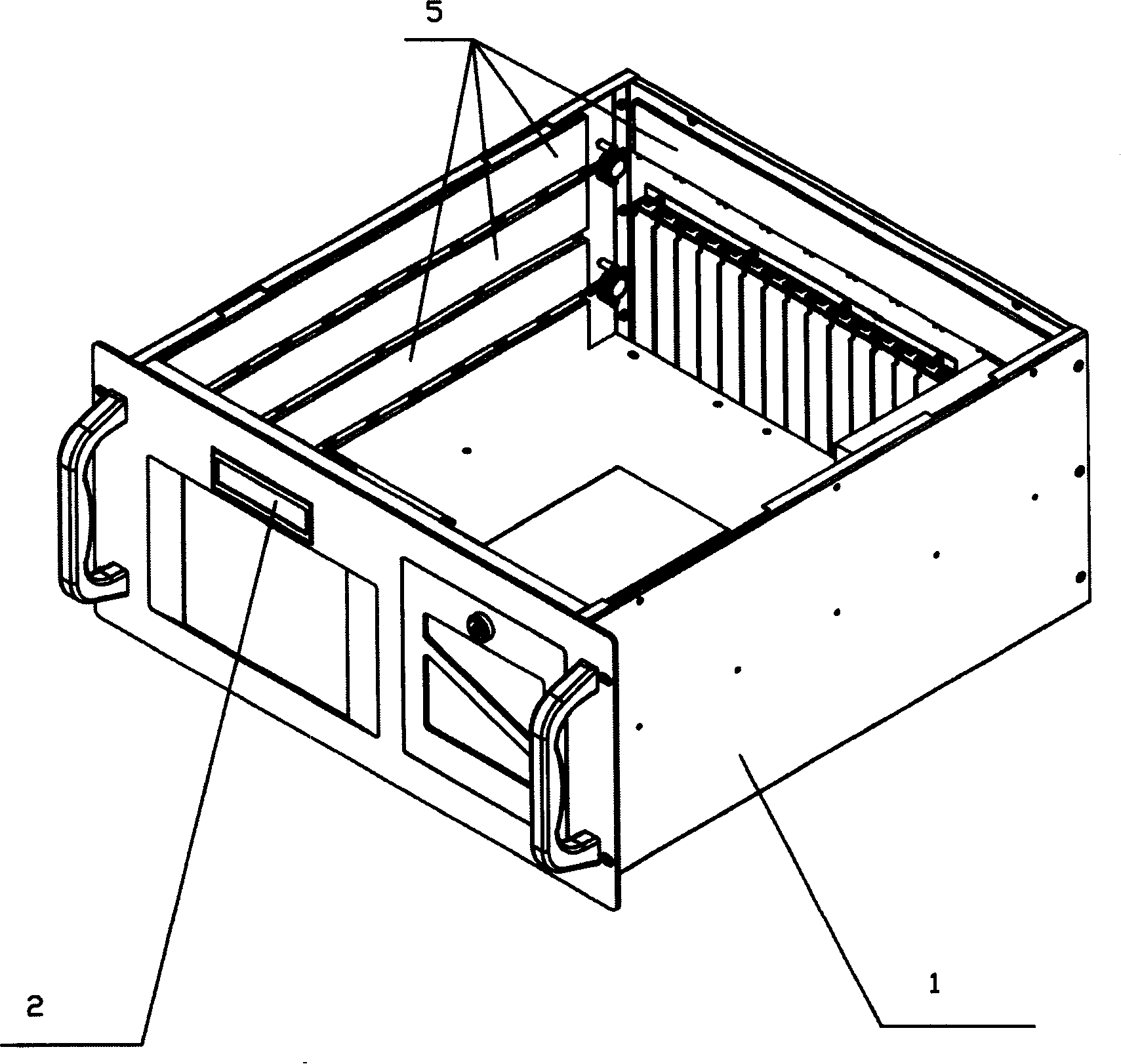
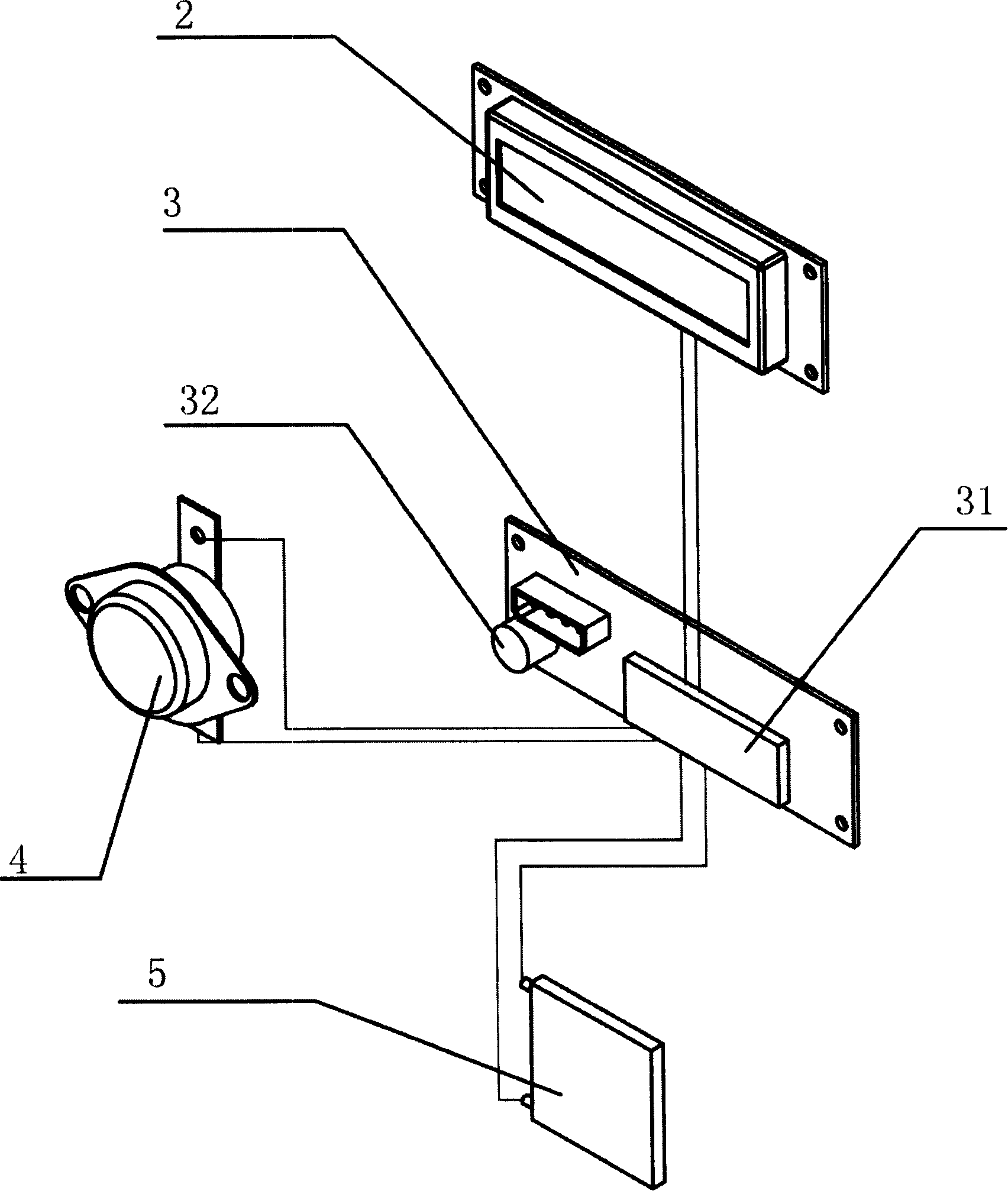
[0021] see Figure 1 to Figure 3 As shown, the automatic temperature control chassis includes a chassis shell 1 and a chassis power supply 7 disposed in the chassis shell 1, a chassis main board 6 and a chassis optical drive 8, wherein the chassis shell 1 is also provided with a cooling and heating device 5 and the temperature control device 3, the cooling and heating device 5 and the temperature control device 3 are connected to the chassis power supply 7 respectively, the cooling and heating device 5 is connected to the temperature control device 3, and the cooling and heating device 5 is connected to the temperature control device 3. The heating device 3 may be a semiconductor cooling and heating device 3 , and may also be a liquid circulation cooling and heating device or other similar devices capable of regulating the cooling and heating...


PUM


Abstract

The invention relates to an automatic temperature control cabinet, which comprises a cabinet casing and a cabinet power supply arranged in the cabinet casing, wherein the cabinet casing is also provided with a refrigerating and heating device and a temperature control device which are mutually connected and are respectively connected with the cabinet power supply. Adopting the automatic temperature control cabinet improves the sealing performance, the mechanical performance of the cabinet, the stability and the high reliability, the product tends to be diversified and practical, is beautiful in model and rich and colorful in overall appearance, presenting a fresh stereo sense to people and reducing the manufacturing cost correspondingly, is also convenient to install, easy to maintain and strong in environment adaptability, and can be widely used in various fields such as a commercial cabinet, an industrial cabinet and a military cabinet. In the adverse weather conditions, the invention can better play a unique advantage, brings people great convenience and lays a solid foundation for popularizing and developing computer technology.

Description

technical field [0001] The invention relates to the field of electronic equipment, in particular to the field of electronic equipment cabinets, in particular to an automatic temperature control cabinet. Background technique [0002] In modern society, with the continuous advancement of science and technology, more and more electronic devices are applied to all walks of life, and the circuits of these electronic devices must be installed in a certain volume of the chassis. For weak current systems such as electronic circuits , although its power consumption is small, but as the integration level of integrated circuits gradually increases, its heat generation becomes larger and larger. At the same time, with the shrinking of integrated circuit volume and the improvement of It is also becoming more and more sensitive. Only by ensuring that the ambient temperature is controlled within a certain range can the normal operation of these electronic circuits be guaranteed. Therefore,...

Claims


Application Information

Patent Timeline
Patent Type & Authority Applications(China)
IPC IPC(8): H05K5/00H05K7/20G05D23/00
Inventor 章冬华
Owner SHANGHAI EVOC INTELLIGENT TECH
Why Eureka
Try Eureka