Digital low-converter

A digital down-converter and filter technology, applied in phase-modulated carrier systems, electrical components, transmission systems, etc., can solve problems such as speed bottlenecks and achieve the effect of reducing processing difficulty

Inactive Publication Date: 2008-06-11
ARTEK MICROELECTRONICS
View PDF0 Cites 12 Cited by
  • Summary
  • Abstract
  • Description
  • Claims
  • Application Information

AI Technical Summary

Problems solved by technology

Therefore, there will still be a speed bottleneck in the connection between the polyphase mixer and the polyphase filter

Method used

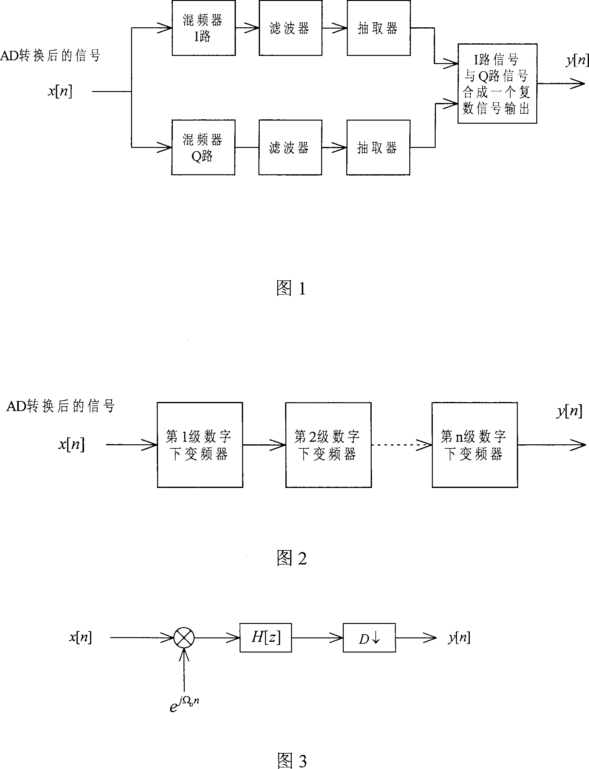

Image

  • Digital low-converter
  • Digital low-converter
  • Digital low-converter

Examples


Embodiment Construction

[0071] When the number of filter groups is equal to the number N of polyphase mixer groups, N is a natural number. It can be seen from Figure 10 that in each branch of the polyphase mixer:

[0072] c j [ l ] = b j [ n ] l = Nn 0 l ≠ Nn - - - ( 5 )

[0073] d [ l ] = Σ j = 0 N - ...


PUM


Abstract

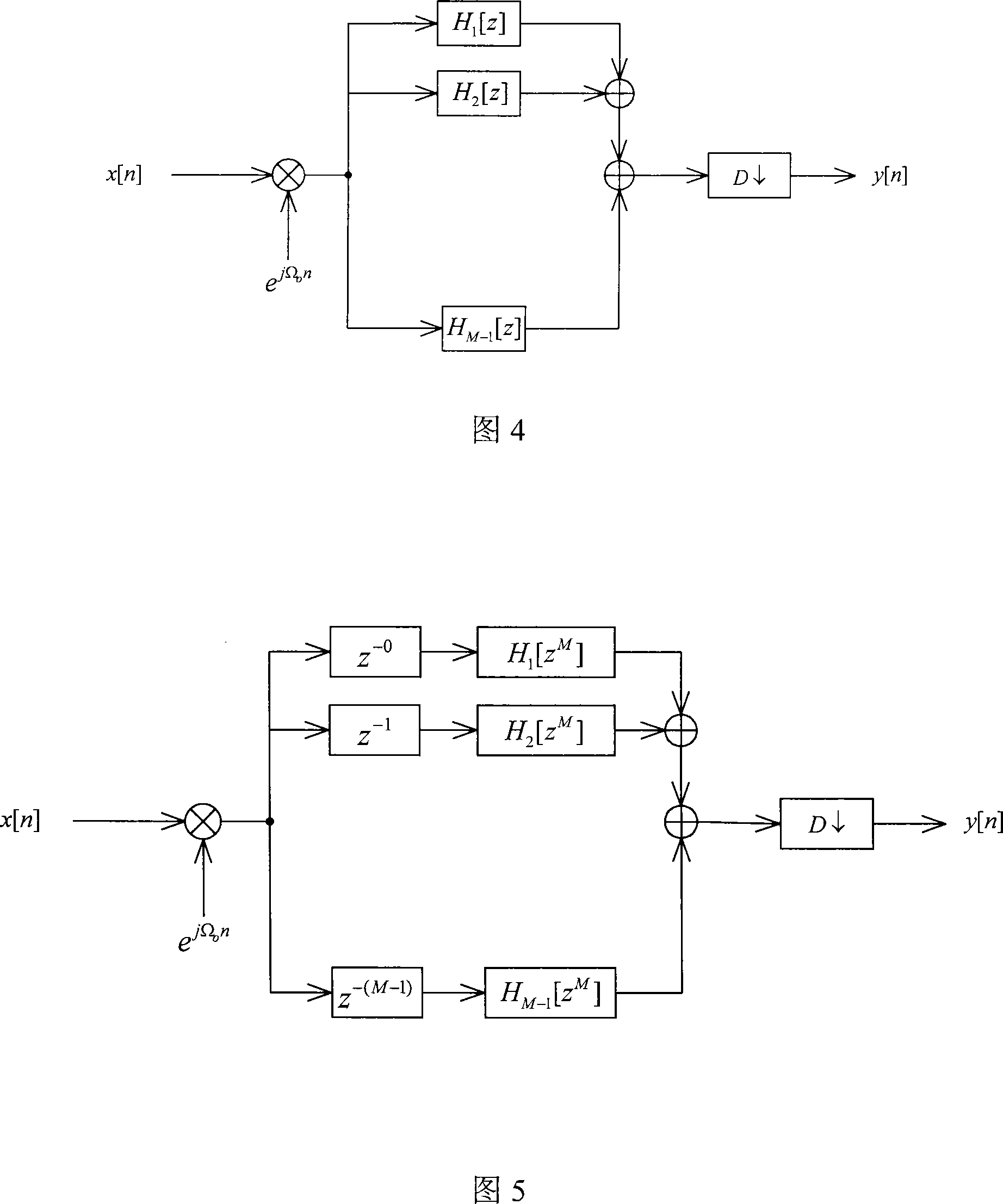
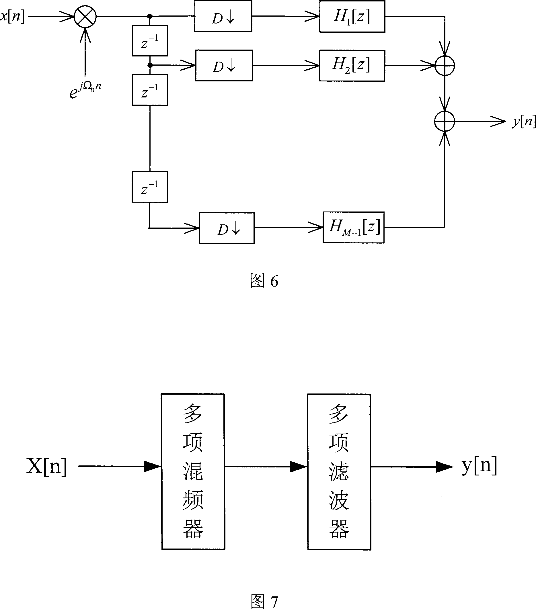
The invention discloses a digital down converter which comprises a signal input end which is used for receiving input signals and a signal output end which is used for outputting signals, wherein, N independent operation branches are arranged between the signal input end and the signal output end; each operation branch comprises an extractor the extraction factor of which is N, a multiphase branch mixer which is constructed according to an N-phase digital mixer, and a multiphase branch filter which is constructed according to an H(z) expression of an N-phase digital filter which are connected with each other in order; input ends of extractors of various operation branches are coupled with the signal input end; outputs of branch filters of various operation branches are outputted to the signal output end through addition by an adder; an i operation branch corresponding to the input signals comprises i-1 clock cycle time delays; N and i are all natural numbers, and i is more than or equal to 1 and less than or equal to N. Arithmetic speed of each operation branch is lowered to be 1 / N of the prior arithmetic speed, and modules for improving the arithmetic speed do not exist because each operation branch is completely independent, thereby processing difficulty of a system is reduced.

Description

technical field [0001] The invention relates to a digital down converter. Background technique [0002] The IF digital receiver is required to be able to realize real-time demodulation of Quadrature Phase-Shift Keying (QPSK) signals with a bandwidth of 100MHz to 200MHz, an IF of 375MHz, and a sampling rate of 500MSPS. In this case, the bandpass sampling theorem can no longer be used. At present, there is no field-programmable gate array (Field-Programmable Gate Array, namely FPGA) chip that can work above 500MHz. In this way, the operating frequency is less than 200MHz after layout and routing. Therefore, parallel algorithms must be used to decompose the amount of computation before real-time processing is possible. For cost considerations, Xilinx's low-cost FPGA is used for verification, which is more limited in speed and scale. [0003] Generally, digital receivers lower the signal to a relatively low intermediate frequency before sampling and demodulating. When the int...

Claims


Application Information

Patent Timeline
IPC IPC(8): H04L27/22H04B1/16
Inventor 彭洪
Owner ARTEK MICROELECTRONICS
Why Eureka
Try Eureka