
Hydrogen permeable film and fuel battery using the same

A fuel cell and permeable membrane technology, applied in fuel cells, fuel cell components, solid electrolyte fuel cells, etc., can solve problems such as hydrogen permeability decline, reduce the decline of electromotive force with time, high hydrogen permeability, high hydrogen permeability, etc. The effect of less deterioration

Inactive Publication Date: 2008-06-04
SUMITOMO ELECTRIC IND LTD +1
View PDF2 Cites 4 Cited by
  • Summary
  • Abstract
  • Description
  • Claims
  • Application Information

AI Technical Summary

Problems solved by technology

If a hydrogen permeable membrane having a Pd film (formed as a coating layer on the surface of a hydrogen permeable substrate mainly composed of V or a V alloy) as described above is used in the temperature range, there is a problem that in the coating layer Interdiffusion between Pd and V or V alloy contained in the hydrogen permeable substrate occurs and the hydrogen permeability decreases with time

Method used


Image

  • Hydrogen permeable film and fuel battery using the same
  • Hydrogen permeable film and fuel battery using the same

Examples


Embodiment 1

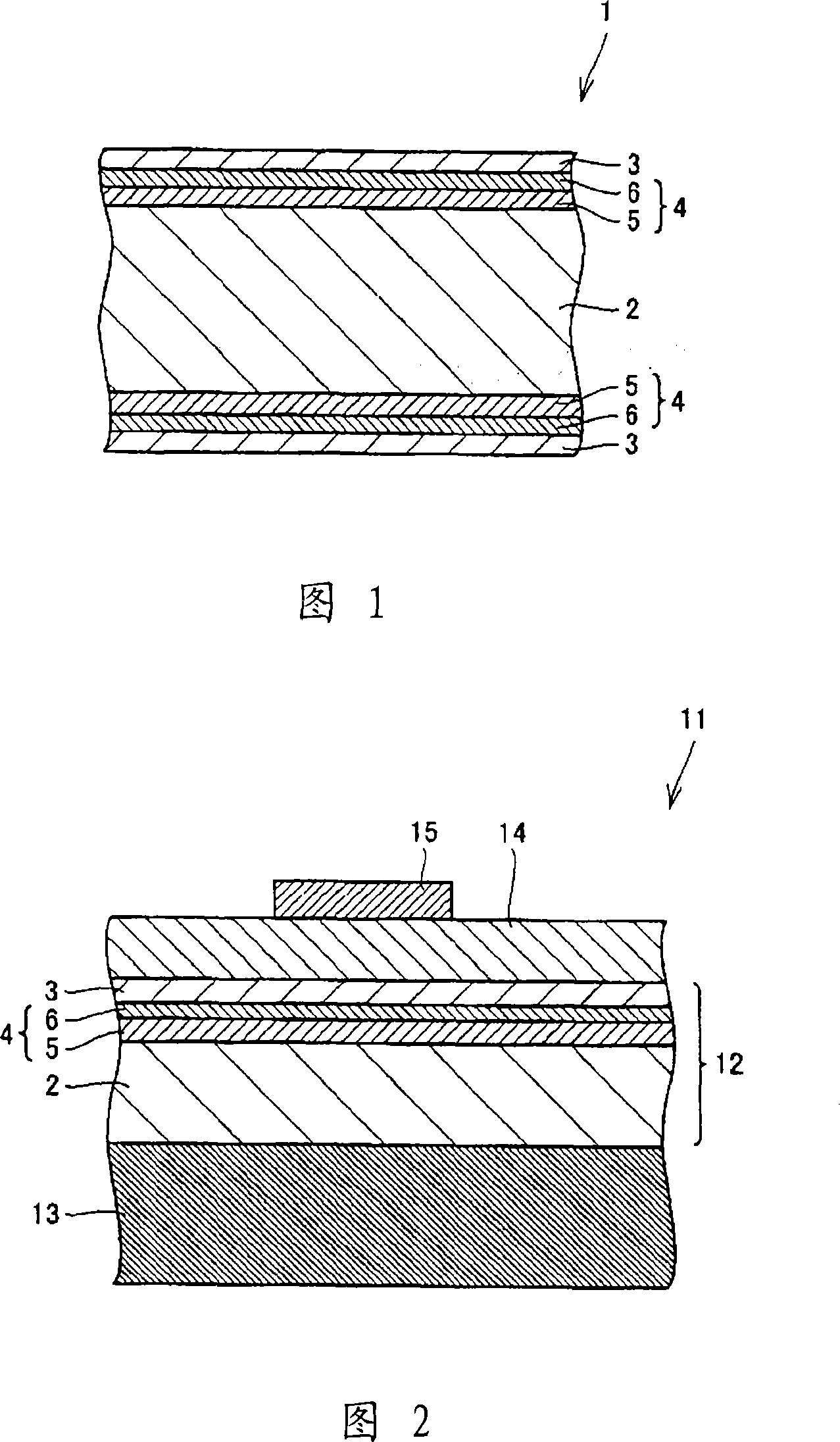
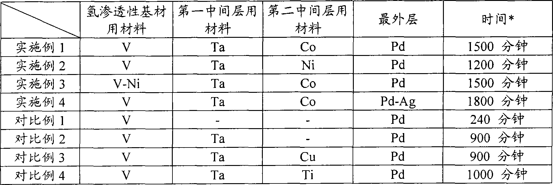
[0062] A commercially available V-foil (disc shape with a diameter of 10 mm and a thickness of 100 μm) with a thickness of 0.1 mm was used as the hydrogen permeable substrate 2, and the vacuum degree was not greater than 2×10 -3 Both surfaces of the V foil were covered with Ta by vapor deposition under Pa and without heating the substrate to form a Ta layer (first intermediate layer 5 ) with a thickness of 0.03 μm (30 nm). Then, similarly, the surface of each Ta layer was covered with Co to form a Co layer (second intermediate layer 6 ) having a thickness of 0.03 μm (30 nm). In addition, similarly, the surface of each Co layer was covered with Pd to form a Pd film 3 with a thickness of 0.1 μm on the outermost layer. Thus, the hydrogen permeable membrane 1 of the example shown in Fig. 1 was produced.

[0063] With respect to the obtained disc-shaped hydrogen permeable membrane 1 having a diameter of 10 mm, the amount of hydrogen permeation per unit time was measured under the ...

Embodiment 2

[0065] Hydrogen permeable membrane 1 was produced in the same manner as in Example 1 except that Ni was used instead of Co to form second intermediate layer 6 . The measurement was performed in the same manner as in Example 1 and it was found that the hydrogen permeation amount decreased by 30% from the initial hydrogen permeation amount at 1200 minutes after the start of the measurement.

Embodiment 3

[0067] A hydrogen permeable membrane 1 was produced in the same manner as in Example 1 except that a commercially available V-Ni foil (disc shape with a diameter of 10 mm and a thickness of 100 μm) with a thickness of 0.1 mm was used as a hydrogen permeable substrate 2 . The measurement was performed in the same manner as in Example 1 and it was found that the hydrogen permeation amount decreased by 30% from the initial hydrogen permeation amount at 1500 minutes after the start of the measurement.


PUM

PropertyMeasurementUnit
thicknessaaaaaaaaaa
thicknessaaaaaaaaaa
thicknessaaaaaaaaaa

Abstract

This invention provides a 1 nm to 100 nm-thick hydrogen permeable film (1) comprising a V- or V alloy-containing hydrogen permeable base material (2), a Pd- or Pd alloy-containing hydrogen permeable Pd film (3), and an intermediate layer (4) provided between the hydrogen permeable base material (2) and the Pd film (3) and comprising a first intermediate layer (5) in contact with the hydrogen permeable base material (2) and a second intermediate layer (6) in contact with the Pd film (3). The first intermediate layer (5) contains at least any of Ta, Nb, and their alloys. The second intermediate layer (6) contains at least any of group 8 elements, group 9 elements and group 10 elements and their alloys. There is also provided a fuel battery comprising the hydrogen permeable film and a proton conductive film provided on the Pd film in the hydrogen permeable film. The hydrogen permeable film can suppress mutual diffusion among the hydrogen permeable base material, the intermediate layer, and the Pd film and can solve a problem of a lowering in hydrogen permeability with the elapse of time. The fuel battery does not cause a lowering in electromotive force with the elapse of time.

Description

technical field [0001] The present invention relates to a hydrogen permeable film having high hydrogen permeability and hydrogen selectivity in which the decrease in hydrogen permeability with time is small, and a fuel cell using the hydrogen permeable film. Background technique [0002] Hydrogen permeable membranes have hydrogen permeability and hydrogen selectivity to selectively permeate only hydrogen from a mixed gas of hydrogen and other gases, and are widely used for extracting hydrogen from hydrogen-containing gases and for fuel cells. [0003] As the hydrogen permeable membrane, various membranes having excellent hydrogen permeability containing Group 5 elements such as vanadium (V), niobium (Nb), tantalum (Ta) and the like or palladium (Pd) have been proposed. Among them, Pd is inferior to Group 5 elements such as V, Nb, Ta, etc. in terms of hydrogen permeability, however, Pd has excellent resistance to oxygen in the outside air, etc. and is excellent in the ability...

Claims


Application Information

Patent Timeline
Patent Type & Authority Applications(China)
IPC IPC(8): B01D71/02B01D53/22B01D69/10B01D69/12H01M8/02H01M8/12
CPCB01D69/12B01D67/0072H01M8/0232Y02E60/50H01M4/8867H01M4/94H01M4/8871C01B3/505B01D71/022B01D67/0069H01M4/92H01M4/8807H01M4/8657H01M8/0245B01D2325/04B01D2325/28Y10T428/12493B01D71/0221B01D71/02232B01D69/1213B01D69/1216B01D71/02231
Inventor 水野修饭岛昌彦
Owner SUMITOMO ELECTRIC IND LTD
Learn More