
Photomask and its manufacture method and pattern definition method

A manufacturing method and a technology of a photomask, which are applied to originals for photomechanical processing, optics, and microlithography exposure equipment, etc., can solve the problem of bending and deformation of the photomask 130, the inability to improve the exposure resolution, and affecting the correctness of the exposure pattern sexual issues

Inactive Publication Date: 2012-10-24
INNOLUX CORP
View PDF0 Cites 0 Cited by
  • Summary
  • Abstract
  • Description
  • Claims
  • Application Information

AI Technical Summary

Problems solved by technology

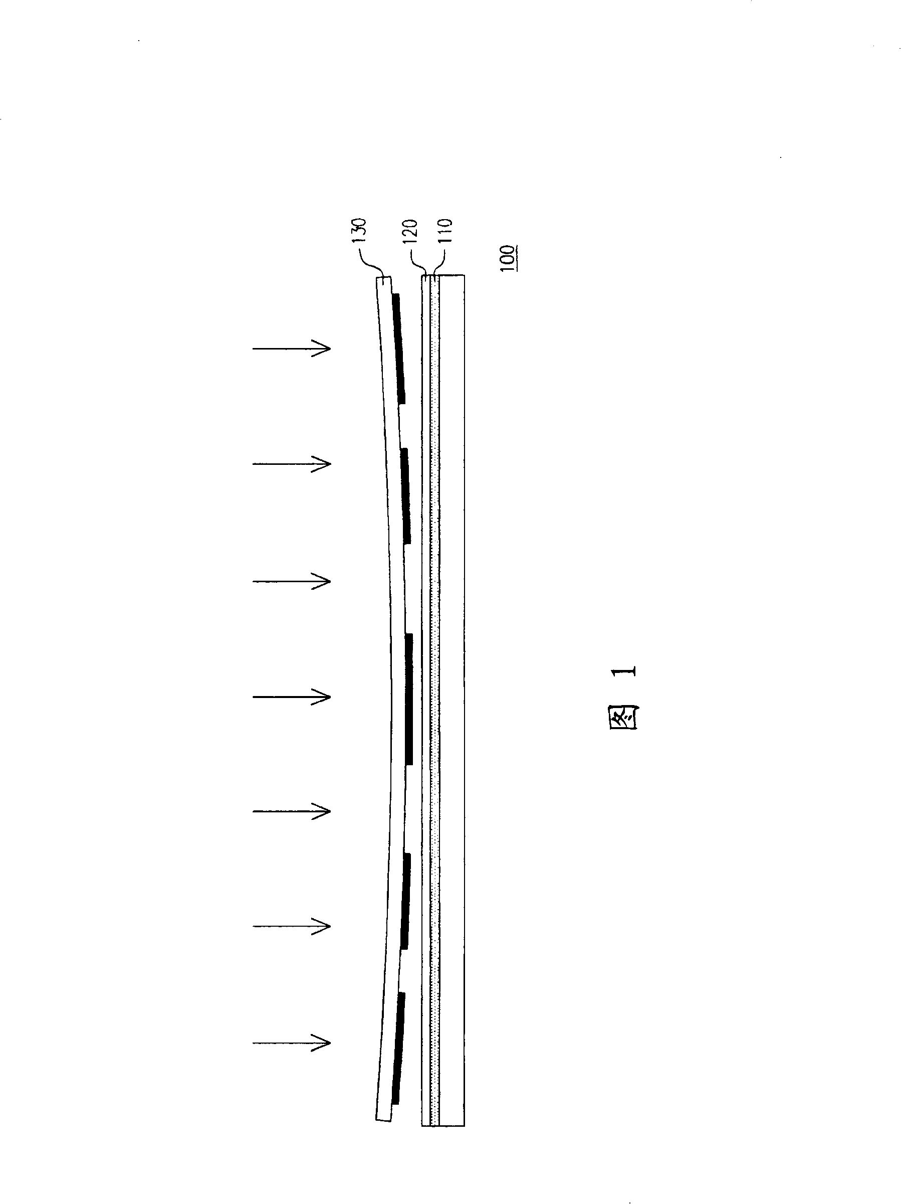
However, when the size of the photomask 130 is getting bigger and bigger, the photomask 130 is easily affected by gravity and deformed, causing the central part of the photomask 130 to be in contact with the photoresist layer 120
In order to avoid the above situation, the distance between the photomask 130 and the photoresist layer 120 cannot be shortened, so that the exposure resolution cannot be improved, and the bending deformation of the photomask 130 makes the contact between the photomask 130 and the photoresist layer 120 difficult. The spacing between the resist layers 120 is different, which will affect the correctness of the exposure pattern

Method used


Image

  • Photomask and its manufacture method and pattern definition method
  • Photomask and its manufacture method and pattern definition method
  • Photomask and its manufacture method and pattern definition method

Examples


Embodiment Construction

[0031] Figure 2A-2C A flow chart of photomask fabrication according to a preferred embodiment of the present invention is shown in sequence. First please refer to Figure 2A , providing a photomask substrate 210 , a surface of the photomask substrate 210 is divided into a pattern area 212 and a non-pattern area 214 . In one embodiment, the material of the photomask substrate 210 is, for example, quartz glass.

[0032] Then please refer to Figure 2B , forming a shielding pattern 220 in the pattern area 212 . In one embodiment, the method for forming the shielding pattern 220 includes photolithography, and the shielding pattern 220 is made of an opaque material, such as metal.

[0033] Please refer to later Figure 2C , a plurality of protrusions 230 are formed in the non-pattern area 214 of the photomask substrate 210 , wherein the height of the protrusions 230 relative to the surface of the photomask substrate 210 is greater than the thickness of the masking pattern 220...


PUM


Abstract

A photo mask comprises a photo mask base plate, a shadowing pattern and a plurality of convex pieces, wherein, one surface of the photo mask base plate can be divided into a pattern area and a non-pattern area outside the pattern area; the shadowing pattern is deployed in the pattern area, while the convex pieces are deployed in the non-pattern area; the height of the convex pieces relative to the surface is greater than the thickness of the shadowing pattern. When the photo mask is used to carry out the step of pattern definition to a to-be-defined base plate, the convex pieces can be in contact with the base plate, and a smaller interval between the photo mask and the to-be-defined base plate is maintained, so as to promote the resolution of pattern definition.

Description

technical field [0001] The present invention relates to a photomask, a method for making the photomask and a method for defining a pattern, in particular to a photomask with raised parts, a method for making the photomask and using the photomask to process a substrate The method of pattern definition. Background technique [0002] The photolithography process has been widely used in the manufacture of various high-tech products such as flat-panel displays and semiconductor devices. It forms various types of flat-panel displays and semiconductors by defining patterns for each stacked material layer. components required for the device. However, under the trend of increasing component integration, the requirements for exposure resolution in the photolithography process are also increasing. [0003] Taking liquid crystal displays as an example, proximity exposure is usually used in the manufacturing process of large-size liquid crystal displays, which has the advantages of low...

Claims


Application Information

Patent Timeline
Patent Type & Authority Patents(China)
IPC IPC(8): G03F1/60G03F1/68G03F7/20B41J2/01H01L21/027G03F1/00
Inventor 丁景隆王程麒
Owner INNOLUX CORP
Learn More