
Rear change converter of wind power generation system and its loop current control method

A technology of back-to-back converters and wind power generation systems, which is applied in wind power generation, single-grid parallel feeding arrangement, etc., can solve the problems of large volume and high cost, improve operational reliability, save costs, and reduce circuit volume. and the effect of switching losses

Inactive Publication Date: 2008-02-13
INST OF ELECTRICAL ENG CHINESE ACAD OF SCI +1
View PDF0 Cites 56 Cited by
  • Summary
  • Abstract
  • Description
  • Claims
  • Application Information

AI Technical Summary

Problems solved by technology

[0006] The invention overcomes the shortcomings of large volume and high cost in the existing parallel structure, and proposes a new parallel converter and its circulation control method

Method used


Image

  • Rear change converter of wind power generation system and its loop current control method
  • Rear change converter of wind power generation system and its loop current control method

Examples


Embodiment Construction

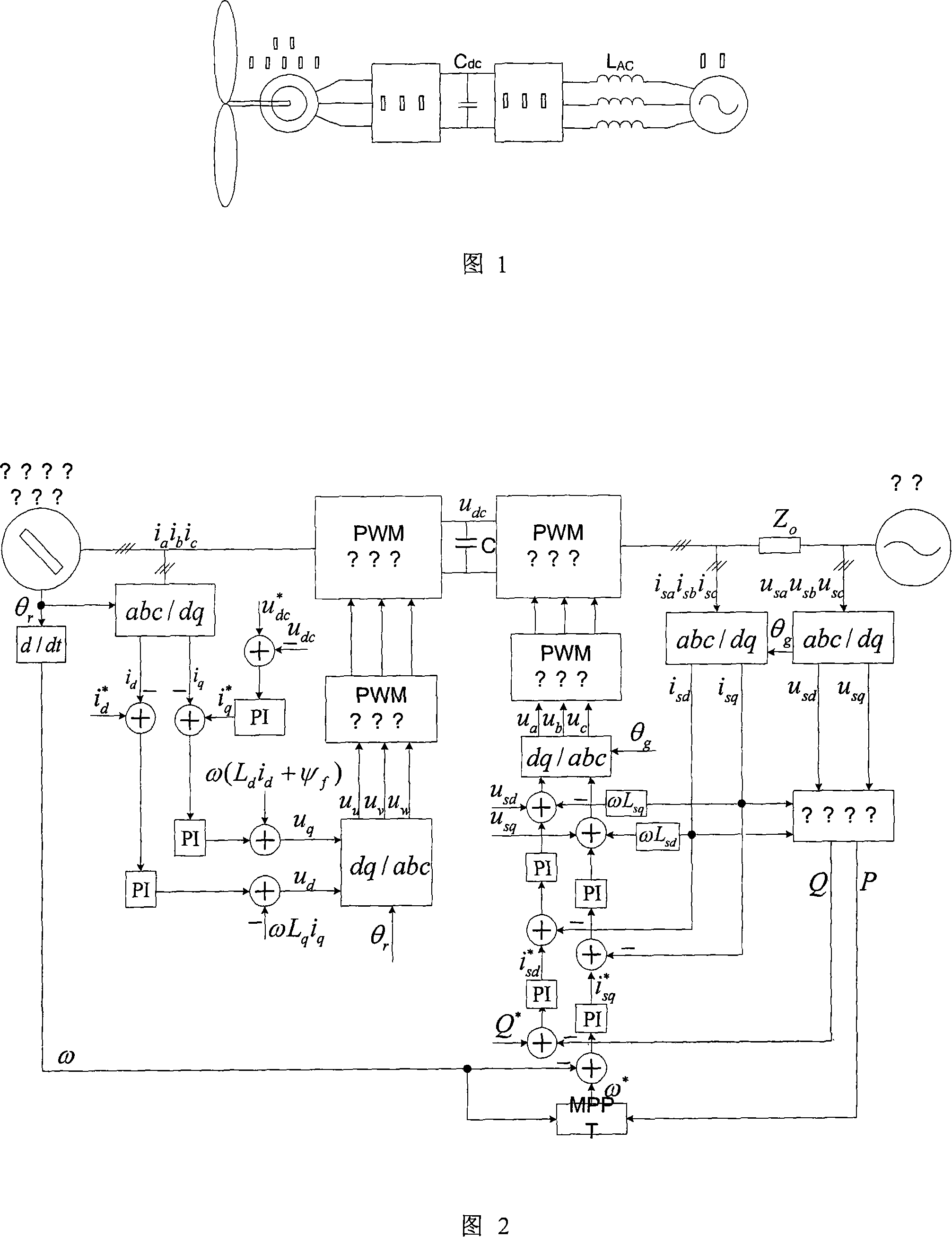
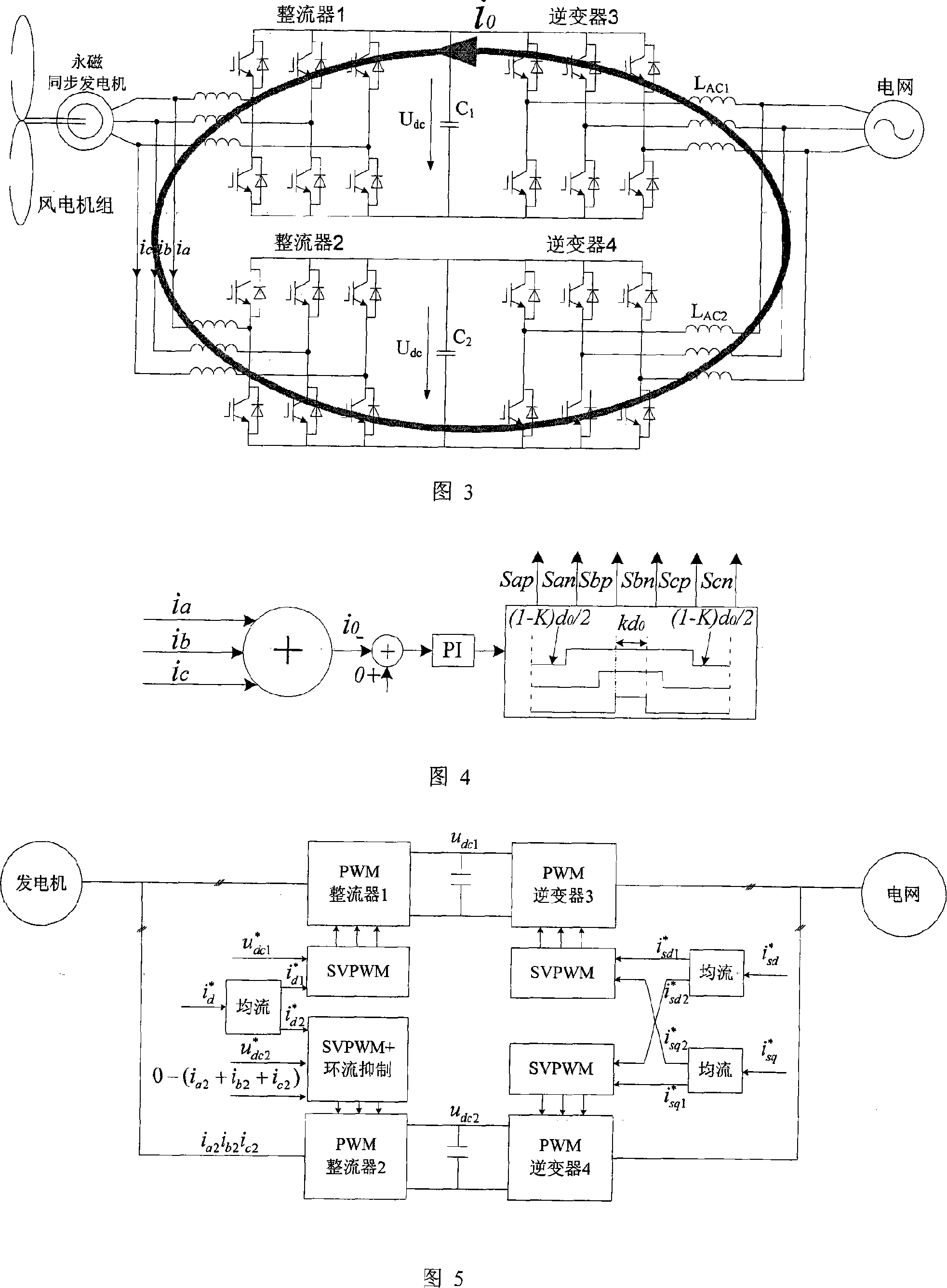
[0026] The working principle and process of the present invention will be described in detail below in conjunction with the accompanying drawings.

[0027] When the wind power generation system involved in the present invention is in operation, there are mainly three working states according to the size of the external wind speed:

[0028] (1) When the wind speed is lower than the rated wind speed of the system, the pitch angle is basically unchanged to maintain the maximum wind energy utilization coefficient. According to the maximum power algorithm, the system obtains the maximum power input to the grid by the system, and thus obtains the optimal speed of the generator. By adjusting the active current of the grid-connected inverter, the output power of the system is maximized, and the motor runs at the optimal speed. Generally, the reactive power is set to zero, which makes the system work at the maximum active power output state and improves the efficiency of the system. W...


PUM


Abstract

The utility model provides a back-to-back convertor of a wind power generation system. Two back-to-back convertors are connected in parallel. Each convertor comprises rectifiers on the side of a motor and an inverter on the side of a grid. The rectifiers on the side of the motor are conncted in parallel. An AC input end is connected with an outlet terminal on the side of a stator of a magneto alternator; direct-current output terminals of the two rectifiers on the side of the motor are connected with an independent voltage-stabilizing large capacitor, respectively. A positive terminal and a negative terminal of each of the capacitors are conneted with an inverter, respectively; output terminals of the inverters are connected to a grid after parallel connection. Each rectifier on the side of the motor is controlled by a digital processing chip DSP. When the two convertors run concurrently, circulatory zero-sequence current of the shunt circuit between the convertors is restricted to bezero; circuit loss is accordingly reduced, and circuit components are protected.

Description

technical field [0001] The invention relates to a converter of a wind power generation system and a method for controlling the circulation thereof. Background technique [0002] With the continuous development of wind power generation technology, the permanent magnet direct drive wind power generation system has received more and more attention because of its low maintenance cost, low noise, and good low voltage ride-through capability. The inverter needs to completely convert the output power of the wind turbine to the grid side, so the power capacity requirement is relatively high. Due to the limitations of the current manufacturing process of power electronic devices, a single back-to-back converter can no longer meet the needs of the development of direct-drive wind power generation systems, so the parallel connection technology of converters has emerged as the times require. [0003] According to the average model of the three-phase rectifier, in a single three-phase r...

Claims


Application Information

Patent Timeline
IPC IPC(8): H02J3/38
CPCY02E10/763Y02E10/76
Inventor 李建林付勋波胡书举赵斌许洪华
Owner INST OF ELECTRICAL ENG CHINESE ACAD OF SCI
Learn More