Composite type cold slag device
A slag cooling device and a composite technology, applied in the field of slag cooling devices, can solve problems such as insufficient output, insufficient cooling of large slag, and influence on combustion in the furnace, and achieve the effects of improving adaptability, ensuring output effect, and enhancing cooling effect
- Summary
- Abstract
- Description
- Claims
- Application Information
AI Technical Summary
Problems solved by technology
Method used
Image
Examples
Embodiment 1
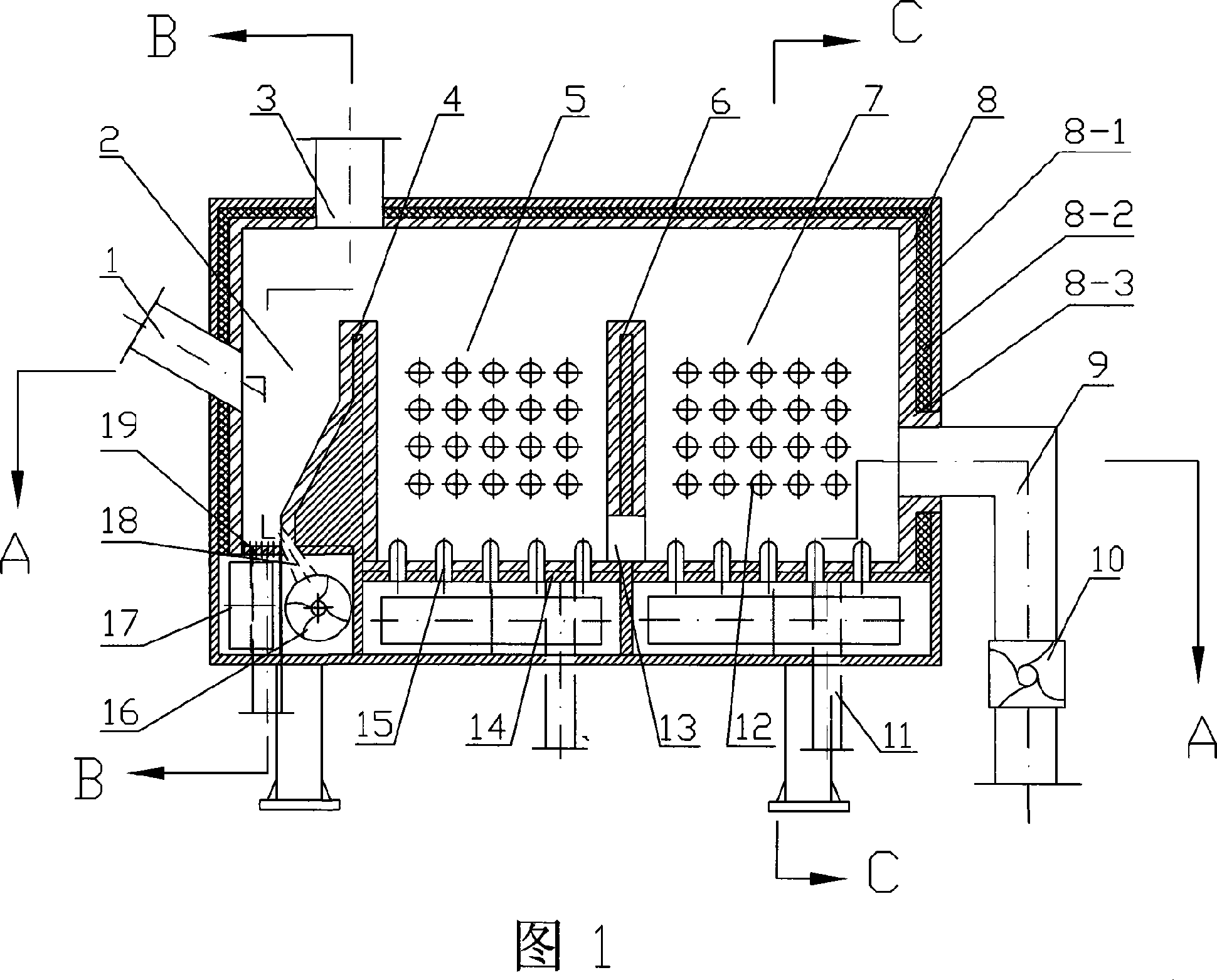
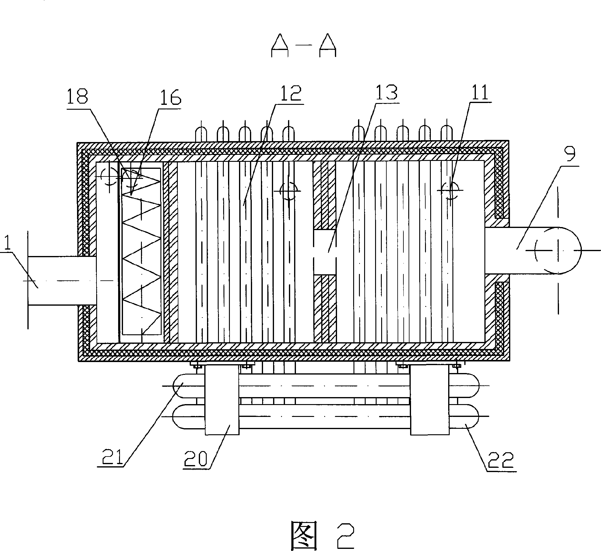
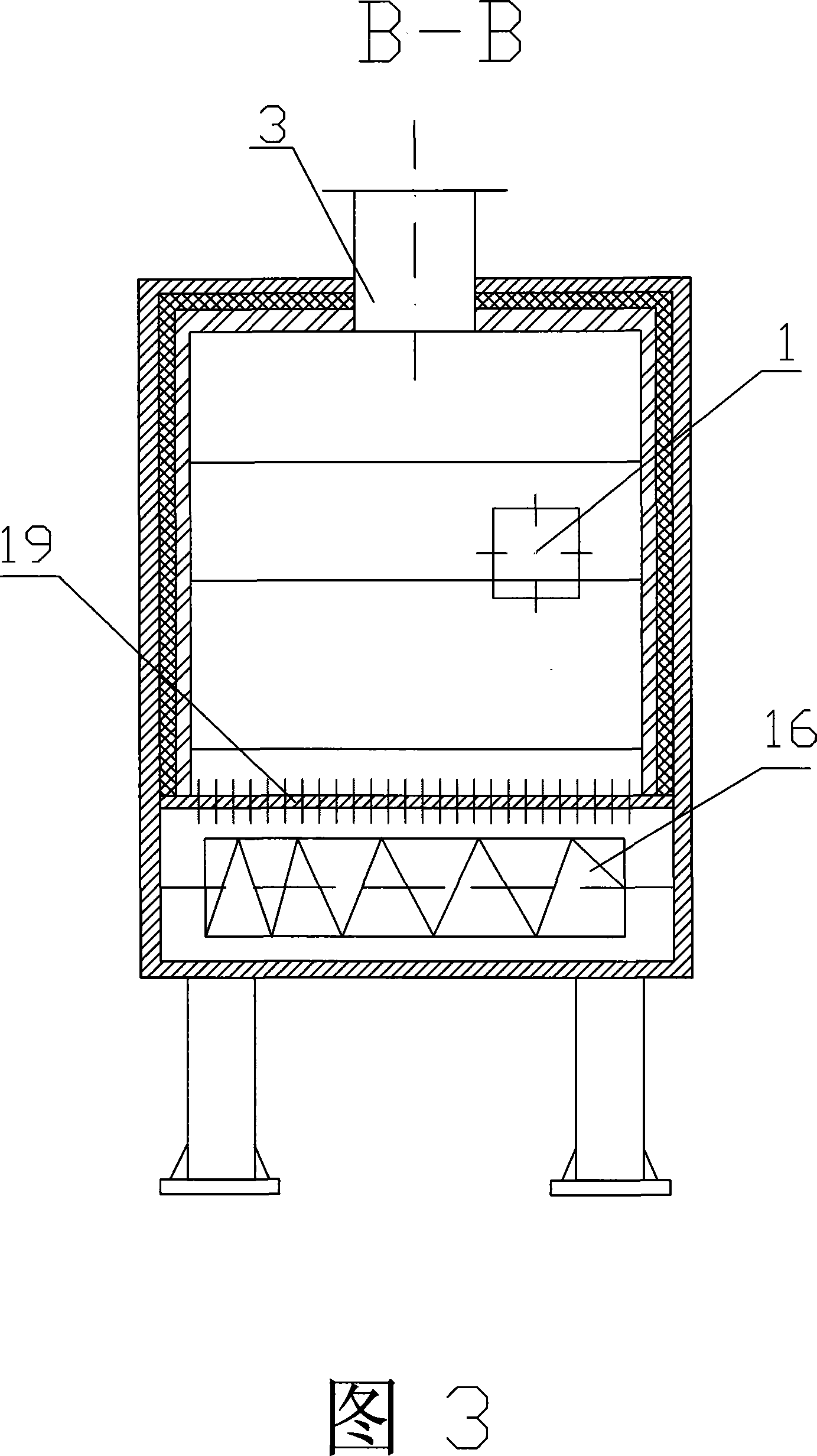
[0027] A kind of composite cold slag device of this embodiment is shown in Figure 1, Figure 2, Figure 3 and Figure 4, and the frame 8-1 of its cold slag chamber 8 is welded into a square body by steel plate, angle steel, channel steel, and internally mixes Insulation layer 8-2 and refractory layer 8-3, the first partition wall 4 and the second partition wall 6 perpendicular to the slag flow direction are arranged in the cold slag chamber 8, the first partition wall 4 and the second partition wall 6 will The inner space of the cold slag chamber 8 is divided into three cooling chambers connected at the upper part: the cooling chamber at the left end is the slag inlet cooling chamber 2, the middle cooling chamber is the first water-cooling chamber 5, and the cooling chamber at the right end is the second water-cooling chamber 7; Independent air chambers 17 are arranged at the lower part of each cooling bin. Among them, a dense-hole air distribution plate 19 is arranged on the lef...
Embodiment 2
[0029] A kind of composite cooling slag device of this embodiment is shown in Fig. 5, Fig. 6 and Fig. 7, and the structural difference with embodiment 1 is: the cold slag chamber 8 has four components in the slag cooling device, consists of frame 8 -1, thermal insulation layer 8-2, refractory layer 8-3, membrane water wall 8-4. The surrounding walls of the slag inlet cooling chamber 2 and the walls of the slag inlet and outlet are all frame 8-1 structures. The frame 8-1 is welded by steel plates, angle steels, and channel steels, and is lined with insulation layer 8-2 and refractory layer 8-3 ; And the front and rear walls and the upper wall of the first water-cooled cooling chamber 5 and the second water-cooled cooling chamber 7 are all made of membrane water-cooled wall 8-4, and membrane-type water-cooled wall 8-4 is welded and connected with frame 8-1. The arrangement of the membrane water wall 8-4 increases the heating surface of the entire slag cooling device and improves...
Embodiment 3
[0031] A composite slag cooling device of this embodiment is shown in Figure 8. The structural difference from Embodiment 1 is that in the structural arrangement of the slag inlet cooling bin 2, the dense-hole air distribution plate 19 is located at the slag inlet cooling bin 2. At the center of the bottom, the ratio of the area of the dense-hole air distribution plate 19 to the cross-sectional area of the upper straight section of the slag inlet cooling chamber 2 is 0.2 to 0.7, and the upper part of the dense-hole air distribution plate 19 is arranged with a straight acceleration section inclined to the left and right sides On the end face, the main large slag discharge pipe 18 is arranged on the dense-hole air distribution plate 19, and the corresponding variable-pitch water-cooled auger slag cooler 16 is arranged at the outlet. Other structural arrangements and cooperation are the same as in Embodiment 1.
[0032] Each cooling chamber in the slag cooling chamber of the ...
PUM
 Abstract
Description
Claims
Application Information
 - R&D
- Intellectual Property
- Life Sciences
- Materials
- Tech Scout
- Unparalleled Data Quality
- Higher Quality Content
- 60% Fewer Hallucinations
Browse by: Latest US Patents, China's latest patents, Technical Efficacy Thesaurus, Application Domain, Technology Topic, Popular Technical Reports.
© 2025 PatSnap. All rights reserved.Legal|Privacy policy|Modern Slavery Act Transparency Statement|Sitemap|About US| Contact US: help@patsnap.com


