Thruster of brake

A technology of pushers and brakes, applied in the direction of brake actuators, etc., can solve the problems of increasing maintenance and repair workload, affecting service life, aging of seals, etc., to reduce maintenance and repair workload, prolong service life and reduce energy consumption Effect

Active Publication Date: 2007-12-12
长沙三占惯性制动有限公司
View PDF1 Cites 2 Cited by
  • Summary
  • Abstract
  • Description
  • Claims
  • Application Information

AI Technical Summary

Problems solved by technology

The disadvantage of the existing pusher is that the driving device of the pusher needs to be in the running state all the time in order to maintain the working state of the braking part during the operation of the pusher, so the energy consumption is large, and the driving device is always in the working state. The heat generated under the running state leads to a high temperature rise, which causes the parts of the pusher to heat up, especially the heat is likely to cause the aging of the seals, which affects the service life, and in severe cases, oil leakage occurs, increasing the workload of maintenance and repairs
In addition, since the release of the working state of the braking part is realized by stopping the operation of the drive device, when the power is cut off, the drive device still has inertia before it stops completely, so the release of the working state of the braking part is slow and cannot Satisfy the working conditions when quick release is required

Method used


Image

  • Thruster of brake
  • Thruster of brake
  • Thruster of brake

Examples


Embodiment Construction

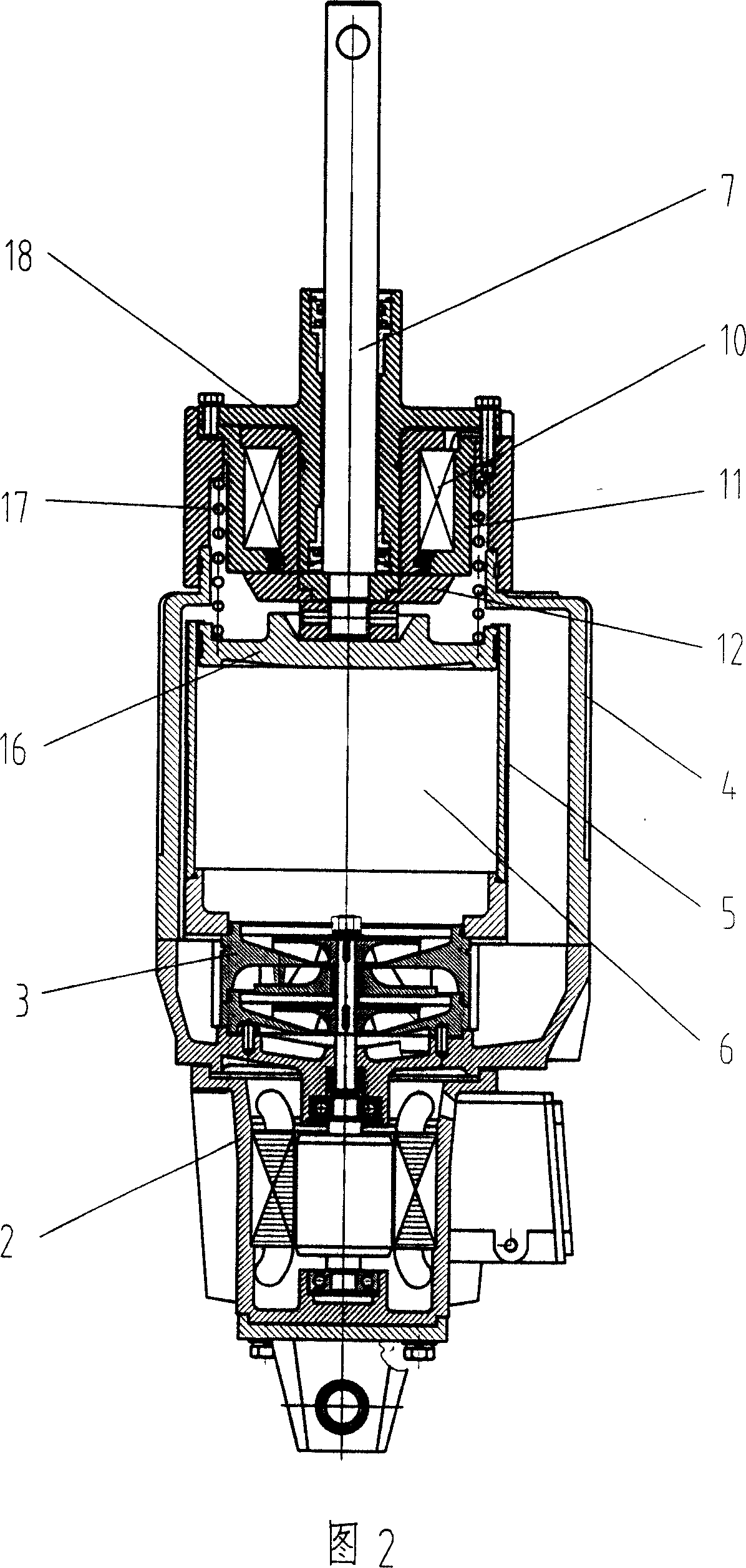
[0017] As shown in Fig. 1 and Fig. 2, the brake is provided with a driving device 2 and a liquid pump 3 driven by the driving device, a liquid storage tank 4 and a hydraulic cylinder 5, the inlet of the liquid pump 3 communicates with the liquid storage tank 4, and the liquid pump 3 The outlet of the hydraulic cylinder communicates with the driving liquid cavity 6 of the hydraulic cylinder 5. The piston rod of the hydraulic cylinder, that is, the push rod 7, is used to be hingedly connected with the driving member 9 of the braking part 8, and an electromagnetic device 10 is provided to keep the braking part 8 in a working state. .

[0018] The driving device 2 can be of different types. As shown in FIG. 2 , the driving device 2 adopts a motor, and the liquid pump 3 is a centrifugal pump. As shown in FIG. 3 , the driving device 2 adopts an electromagnet, and the liquid pump 3 is a plunger pump integrated with the electromagnet.

[0019] There are many configurations of the ele...


PUM


Abstract

The pusher of brake consists essentially of drive (2), liquid pump (3), liquid storing box (4) and hydraulic cylinder (5), the inlet of liquid pump (3) is connected with the liquid storing box (4), outlet of liquid pump (3) is connected with the driving fluid cavity (6) of hydraulic cylinder (5), the piston rod of hydraulic cylinder (5), namely the pushing bar (7) is used for the driving components hinge connection of brake part (8), the invention is equipped with electromagnetic device (10) used for maintaining work condition of brake part (8), said electromagnetic device (10) is installed below the hydraulic cylinder (5), the static iron core of electromagnetic device (10) is connected with the bulk of pusher, the movable iron core of electromagnetic device (10) is connected with the lower of the piston rod namely the pushing bar (7), said electromagnetic device (10) is installed on the brake arm of brake part (8) or is installed on the driving component (9) of brake part (8).

Description

technical field [0001] The invention relates to the field of brakes, in particular to the improvement of the pusher of the brake. Background technique [0002] Patent document No. CN2605419Y published on March 3, 2004 discloses a "long-life brake", which is composed of a braking part and a pusher. The existing pusher structure includes a driving device, an oil pump driven by the driving device, an oil storage tank, and a hydraulic cylinder. The inlet of the oil pump communicates with the oil storage tank, and the outlet of the oil pump communicates with the driving oil chamber of the hydraulic cylinder. The piston rod of the cylinder, that is, the push rod, is used for the hinged connection of the driving member in the brake part, and the brake part realizes the working state (brake or release brake) when the pusher works. The disadvantage of the existing pusher is that the driving device of the pusher needs to be in the running state all the time in order to maintain the w...

Claims


Application Information

Patent Timeline
Patent Type & Authority Applications(China)
IPC IPC(8): F16D65/18
Inventor 谢兴云
Owner 长沙三占惯性制动有限公司
Why Eureka
Try Eureka