Integral sealing electric obstructing instrument

A technology of overall sealing and barriers, applied in roads, restricted traffic, roads, etc., can solve the problems of surrounding environmental pollution, complex structure, large road area occupied by construction, etc.

Inactive Publication Date: 2010-10-06
卢国骥
View PDF10 Cites 0 Cited by
  • Summary
  • Abstract
  • Description
  • Claims
  • Application Information

AI Technical Summary

Problems solved by technology

Therefore, it will take a while for the blocking pile to rise. As the weight of the blocking pile increases, the time required for rising will be longer, so the lifting is slow.
[0005] 3. The sealing performance is poor, and the components are susceptible to corrosion: the existing lifting barriers such as Figure 4 As shown, the hollow frame supporting the barrier is buried below the ground, and the frame is made of a hollow structure to reduce weight. Even if an outer guard shell is added in the pit to separate the barrier from the pit wall, underground moisture, etc. It can also corrode the hollow frame and the pneumatic lifting device in it, so the barrier is susceptible to corrosion, which affects the service life
[0006] 4. Complex structure and large volume: Since the existing liftable barrier is a steel frame pneumatic structure, it is necessary to set up a long-distance air compressor, a gas storage tank, and a gas transmission pipeline. The equipment system is huge and the structure is complex , consumes steel, and maintenance needs to be disassembled as a whole, which is inconvenient
[0007] 5. The amount of construction is large, the construction takes up a long time on the road surface, and the installation cost is high: such as Figure 5 As shown, the supporting frame is a hollow structure. In order to prevent the rainwater flowing into the pit from accumulating in the pit, it is necessary to set up the drainage pipeline system 04 and 05 in the pit 03, and also dig trenches and lay the transmission pipeline 06. The high-pressure gas generated by the air compressor is delivered to the barrier. This design requires a large amount of construction and often damages the road surface. The construction occupies a large area of ​​the road surface and is likely to pollute the surrounding environment. It takes a long time and the installation cost is high.

Method used


Image

  • Integral sealing electric obstructing instrument
  • Integral sealing electric obstructing instrument
  • Integral sealing electric obstructing instrument

Examples


Embodiment 1

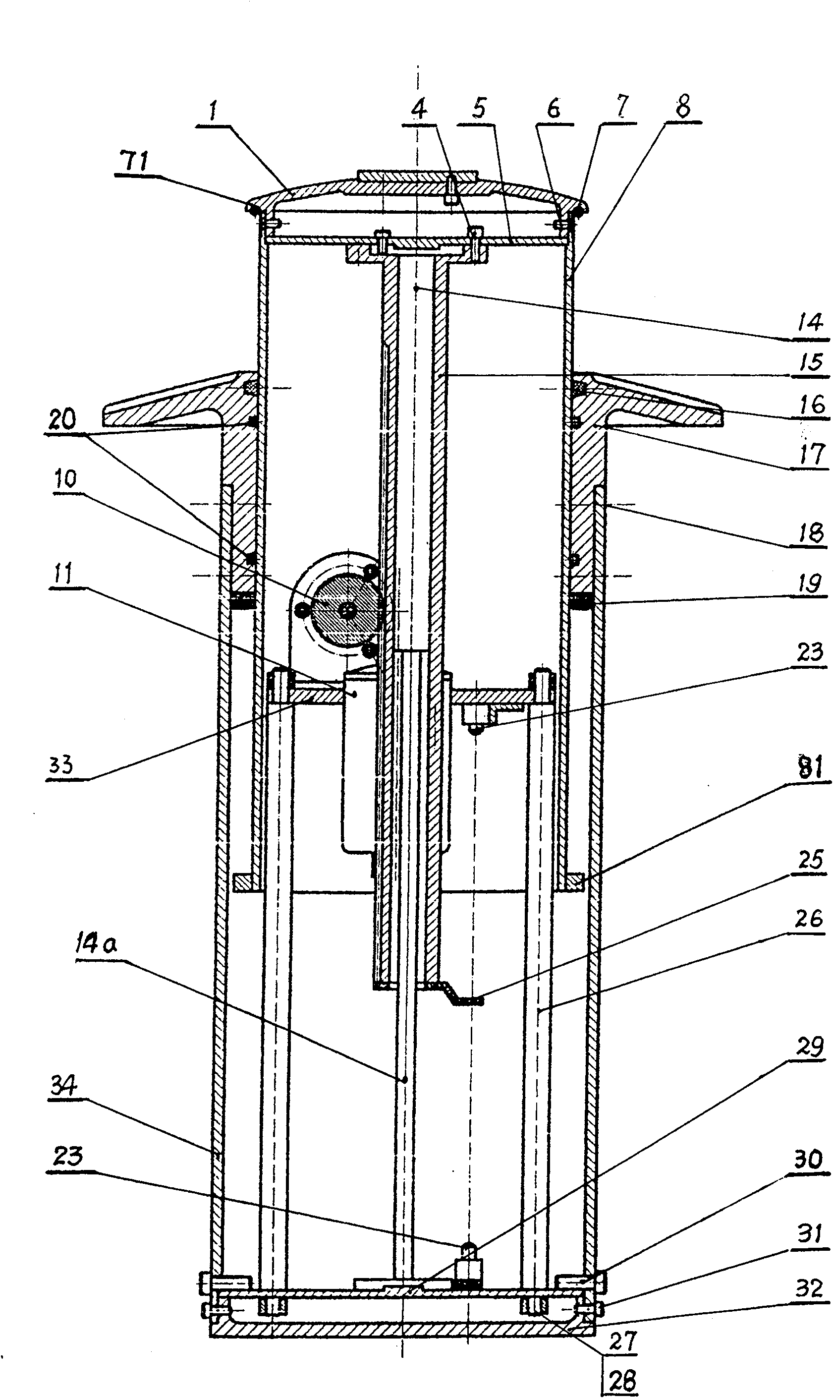
[0055] Such as figure 1 As shown, the integrally sealed electric barrier provided by the present invention includes a barrier seat, which includes a lower cover 34 made of polyethylene engineering plastics, and a flange is provided on the upper surface of a bottom cover 32, which is inserted into the lower cover. 34, on the side wall of the lower cover 34, hexagon socket screws 31 are set to fix the flanges of the lower cover 34 and the bottom cover 32 so that the bottom cover 32 is fixed on the lower cover 34, thus, the lower end of the lower cover 34 is sealed by the hexagon socket screws 31. A metal bottom cover 32 has been fixedly connected, and a lower plate 29 is fixed on the upper flange of the bottom cover 32. On the side wall above the lower plate 29, a number of hexagon socket screws 30 are evenly screwed in the circumferential direction, and one end of the screw rod of the screw is The lower cover 34 is inserted into the upper surface of the lower plate in a sealed...

Embodiment 2

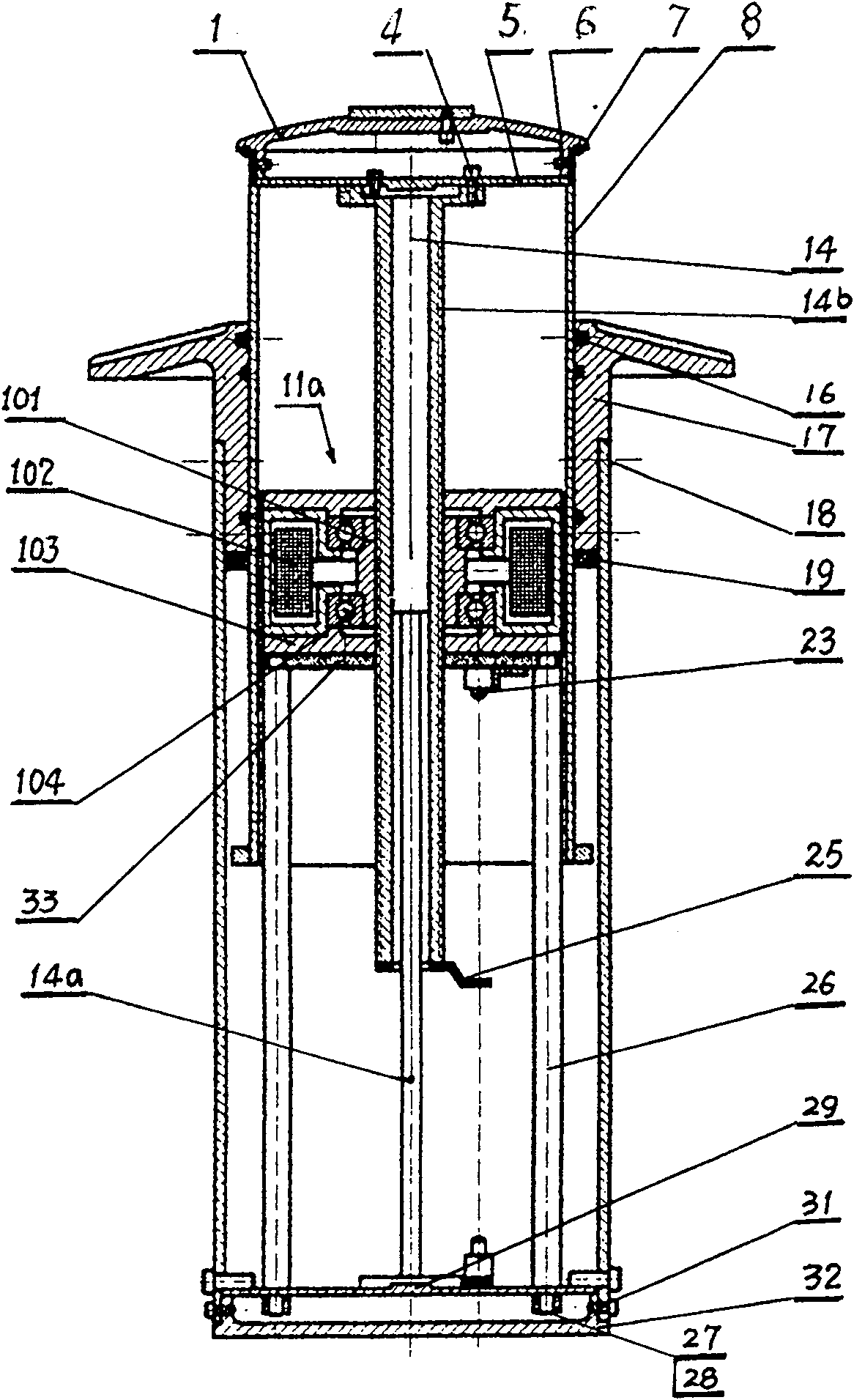
[0068] Such as figure 2 Shown is another structure of the integrally sealed electric barrier. The structure of the barrier seat, the barrier pile, and the gravity balancer is basically the same as that of Embodiment 1, the difference is that the balance cylinder in the gravity balancer is driven to move up and down relative to the piston, and then drives the barrier pile relative to the barrier. The transmission mechanism in the driving source for the rise and fall of the seat, the rack and pinion transmission mechanism is a screw transmission mechanism. Such as figure 2 As shown, threads are provided on the outer peripheral wall of the cylinder body of the balance cylinder 14 to form a threaded cylinder 14 b, or threads are directly processed on the outer wall of the balance cylinder 14 . Similarly, the upper end of the balance cylinder is fixed on the upper top plate 5 of the barrier pile, and the lower end of the piston rod 14a is fixed on the lower plate 29 on the barr...

Embodiment 3

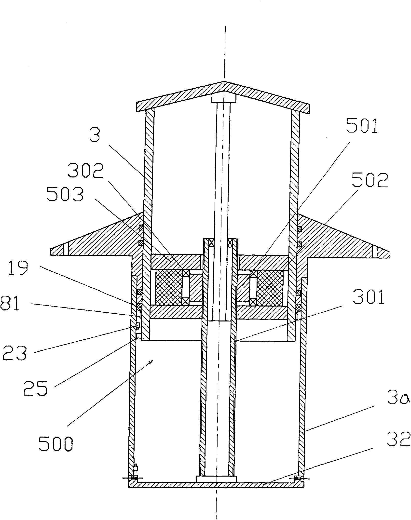
[0072] Such as Figure 2a As shown, in this embodiment, the transmission device is still a screw transmission mechanism, but its structure can be changed to: a cylinder 301 is tightly fitted on the outer peripheral wall of the cylinder body of the balance cylinder, and a cylinder 301 is arranged on the cylinder side wall. Screw threads are provided to form a threaded cylinder, and the end of the balance cylinder is fixed on the bottom cover 32 on the barrier seat, or is fixed on the lower plate fixed on the bottom cover (in the figure) as in the previous embodiment. not shown), the end of the piston rod is fixed on the closed upper bottom plate of the barrier pile, that is, the upper cover 1, or on the upper bottom plate, that is, the upper top plate (not shown) that is arranged below the upper cover 1 A screw hole is provided in the middle of the rotor 501 of the motor 500, and the rotor 501 of the motor is screwed on the threaded cylinder 301 of the balance cylinder; the sta...


PUM


Abstract

The invention provides an integral sealed electric barrier device, comprising a seat of barrier device and a barrier pile. The barrier pile inserts into the barrier device hermetically to form a sealing space. A support is fixed on the upper end of seat of barrier device and the outer peripheral side wall extends out to form a support plate. A bottom cover is fixed on the lower end of seat of barrier device separately. Two parts in a gravity balancer, which can move relatively in vertical direction, are set in the sealing space. Thereinto, the upper part is fixed with the barrier pile and thelower part is fixed with the seat of barrier device. A driving source comprises a motor and a transmission mechanism which can transfer rotation into linear motion. The integration is set in the sealing space. The motor is connected with the driving part of transmission mechanism and the driven part is connected with one part in the gravity balancer. The barrier device can only use electric energy to lift the barrier pile by utilizing gravity balance technology. There is no relation between energy consumption and self-weight of barrier pile in basic. There is little energy consumption but thebarrier pile ascends quickly. The barrier device is provided with good integrity and tightness, simple and convenient construction and long service life.

Description

technical field [0001] The invention provides an electric barrier, especially an integral and fully sealed electric barrier. Background technique [0002] At present, the known liftable barrier is composed of three parts: a driving source, a barrier, and a connecting pipeline. The barriers in the prior art are all split, and the driving source is a hydraulic press or an air compressor. In the barrier device in the prior art, the driving source is placed in one place, and the barrier device is set in another place, for example, as a road barrier pile, the lift-type barrier is set in the middle of the road, and the driving source is set in the roadside. The connection structure between the driving source and the blocker is connected to the cylinder in the blocker through a pipeline, and the hydraulic pressure or air pressure acts on the piston in the cylinder to push the block pile connected to it up and down. Since the driving source of the existing barrier is separated from...

Claims


Application Information

Patent Timeline
Patent Type & Authority Patents(China)
IPC IPC(8): E01F13/04
Inventor 卢国骥
Owner 卢国骥
Why Eureka
Try Eureka