
Infrared detector structure based on micro-bridge resonator and manufacturing method

A technology of infrared detectors and resonators, which is applied in the direction of electric radiation detectors, radiation pyrometry, instruments, etc., can solve the problems of difficult to increase the dielectric temperature coefficient value of pyroelectric thin films, the decrease of ferroelectric pyroelectric performance, Incompatibility with IC technology and other issues, to achieve the effects of easy arrayization and system integration, good long-term stability, and low power consumption

Inactive Publication Date: 2007-10-31
CHINA JILIANG UNIV
View PDF0 Cites 27 Cited by
  • Summary
  • Abstract
  • Description
  • Claims
  • Application Information

AI Technical Summary

Problems solved by technology

Although the pyroelectric infrared detector theoretically has the potential to make the noise equivalent temperature difference (NETD) reach 1mK, it has the following disadvantages: (1) It is not compatible with the IC process and is limited by the high temperature tolerance of the readout circuit (ROIC) It is difficult to increase the dielectric temperature coefficient value (TCD value) of the pyroelectric film
(2) The pyroelectric infrared detector has no DC response, and a chopper must be used to periodically change the incident radiation at an appropriate frequency in order to obtain a signal corresponding to the infrared radiation
(2) The pyroelectric performance of many ferroelectrics decreases as the thickness decreases
[0009] To sum up, photon detectors have high sensitivity and fast response speed, but generally need to work at low temperature (especially for the mid- and far-infrared bands), and their complex structures limit their applications.
Although thermal detectors can work at room temperature, their detection rate and response rate are low, and their response speed is slow, which limits their application.

Method used


Image

  • Infrared detector structure based on micro-bridge resonator and manufacturing method
  • Infrared detector structure based on micro-bridge resonator and manufacturing method
  • Infrared detector structure based on micro-bridge resonator and manufacturing method

Examples


Embodiment

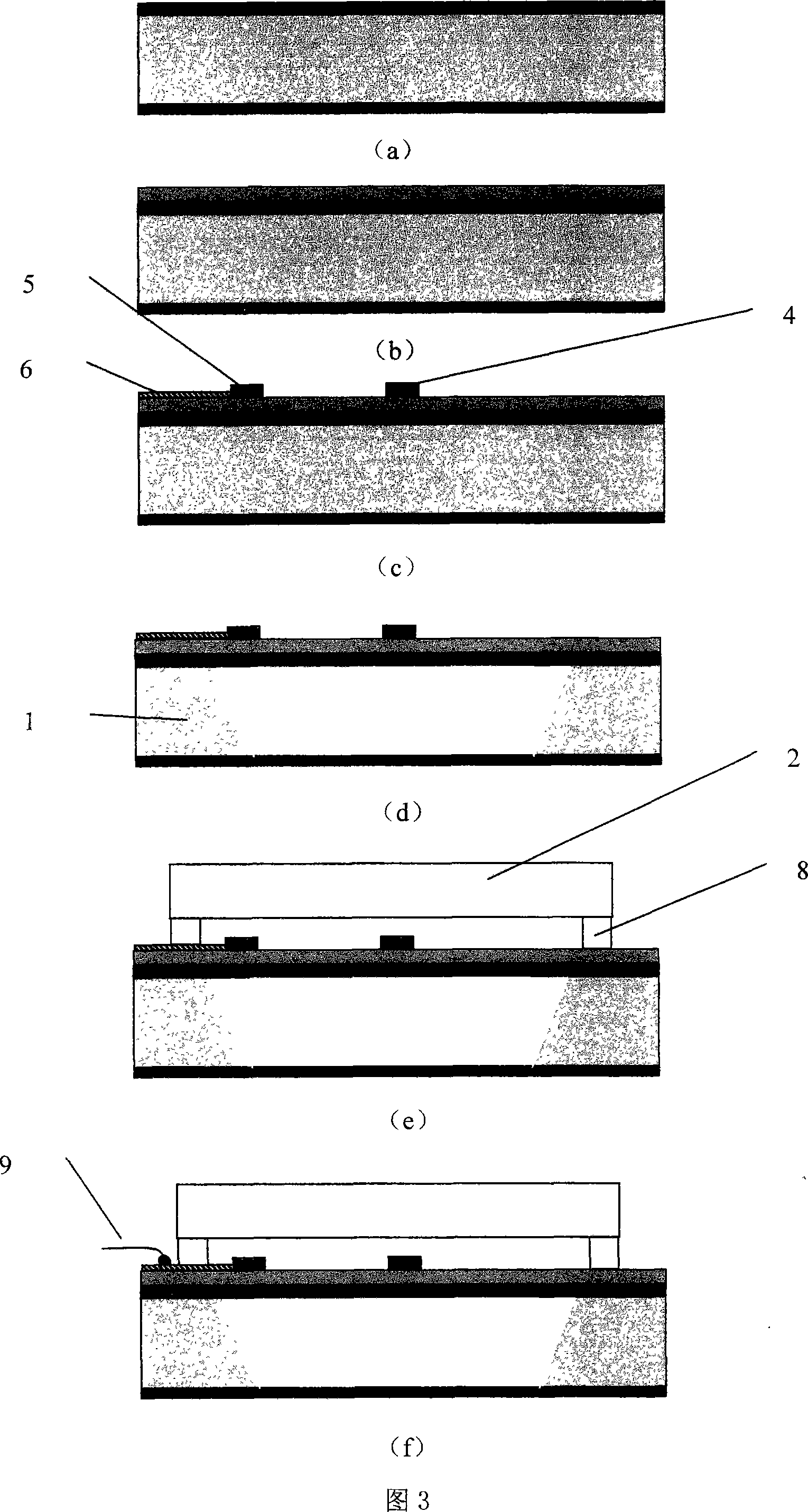
[0037] The technical scheme of the invention is used to manufacture an uncooled infrared detector based on electrothermal excitation / piezoresistive detection micromechanical bridge resonators. Its production process is as follows:

[0038] 1) The original silicon wafer is an N-type, (100) plane silicon wafer with a resistivity of 1-10Ω.cm. Thermal oxidation, oxide layer thickness 0.5μm. (see accompanying drawing 3(a)).

[0039] 2) Deposit a silicon nitride film with a thickness of 0.2-0.3 μm by a low-pressure chemical deposition (LPCVD) process. Lithographic micromechanical bridges on the front side3. (see accompanying drawing 3(b)).

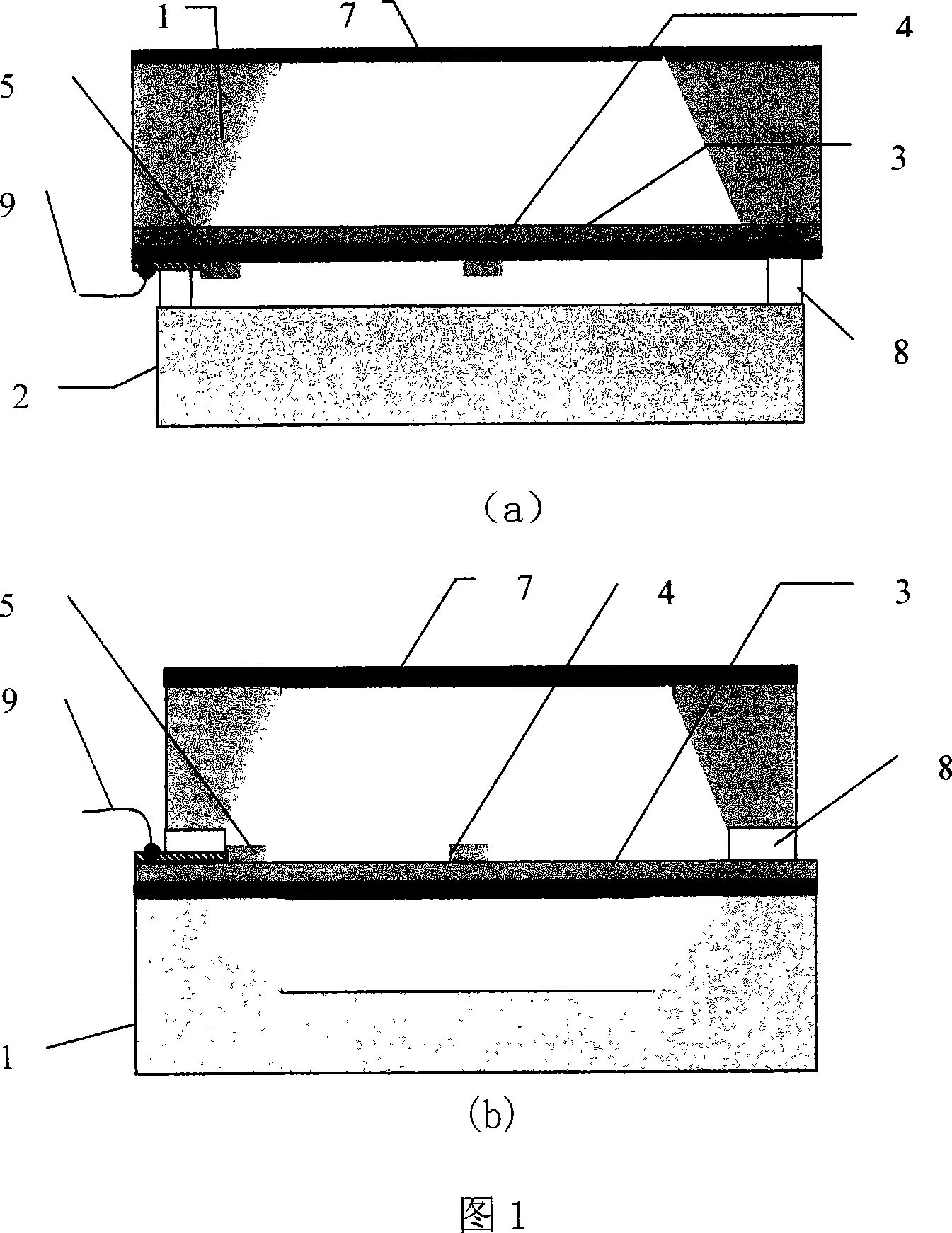
[0040] 3) Deposit polysilicon on the front side to make polysilicon resistors to form the excitation resistor 4 and the pickup resistor 5 . Sputtering aluminum film, photolithographic aluminum wiring, alloying, forming the inner lead 6. (see accompanying drawing 3(c)).

[0041] 4) Deposit a silicon dioxide protective layer on the front si...


PUM


Abstract

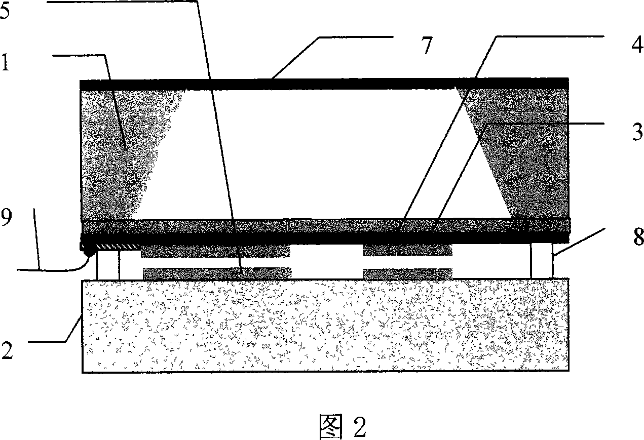
This invention discloses one infrared detector structure and process method based on micro mechanic bridge resonance device, wherein the detector is composed of bridge resonance chip and cover board through vacuum sealing technique or gas sealing technique; the incidence infrared line is to micro mechanic bridge surface through infrared incidence window to lead the bridge temperature rise and to add axis stress force and to lower resonance frequency to reflect incidence infrared strength.

Description

technical field [0001] The invention relates to a structure and a manufacturing method of an infrared detector, in particular to a structure and a manufacturing method of an infrared detector based on a micromechanical bridge resonator, and belongs to the field of micro-electromechanical systems (MEMS). Background technique [0002] Infrared detectors are photoelectric sensors that respond to infrared radiation. It was first used in the military field, such as ground, air and space-based surveillance and targeting systems, weapon night sights, aircraft navigation and driving systems, night fire control systems, etc. At present, the application fields of infrared detectors have been extended to a broader civilian field including non-contact temperature measurement, gas analysis, infrared imaging, etc. [0003] According to the working principle, infrared detectors can be divided into two categories: cooled photon detectors and uncooled thermal detectors. [0004] The basic ...

Claims


Application Information

Patent Timeline
Patent Type & Authority Applications(China)
IPC IPC(8): G01J5/20G01J5/44
Inventor 韩建强卢少勇
Owner CHINA JILIANG UNIV
Learn More