
Catalytic conversion method for increasing propylene production

A catalytic conversion method and propylene technology, applied in chemical recovery, organic chemistry, hydrocarbon cracking and hydrocarbon production, etc., can solve the problems of high reaction temperature and high yield, achieve low dry gas yield, improve yield and selectivity, The effect of increasing the yield of propylene

Active Publication Date: 2007-10-31
CHINA PETROLEUM & CHEM CORP +1
View PDF10 Cites 17 Cited by
  • Summary
  • Abstract
  • Description
  • Claims
  • Application Information

AI Technical Summary

Problems solved by technology

[0006] Although higher yields can be obtained when adopting the third type of method to produce low-carbon olefins such as propylene in the above-mentioned prior art, a high reaction temperature is required simultaneously, and an excessively high reaction temperature will lead to high C2 - Yield

Method used


Image

  • Catalytic conversion method for increasing propylene production

Examples


Embodiment approach

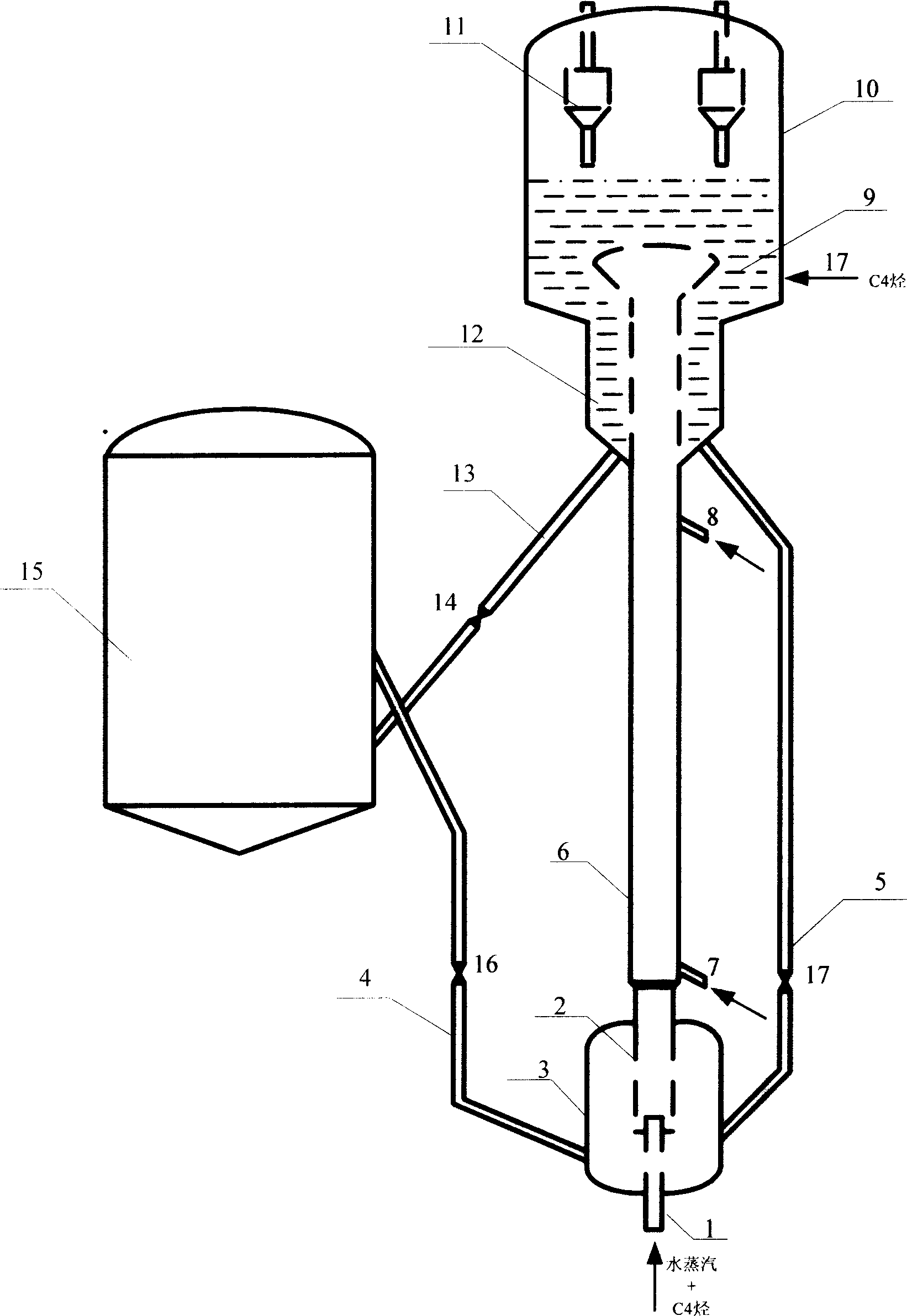
[0025]Embodiment: For the combination reactor of riser + fluidized bed (the fluidized bed is located at the top of the riser), a mixing zone is set at the bottom of the reactor. Its structural features are: along the vertical direction from bottom to top, there are mutually coaxial mixing zone, riser (ie, light hydrocarbon reaction zone), and fluidized bed (ie, heavy hydrocarbon reaction zone). The size of the mixing zone is equivalent to the stripping section in the catalytic cracking unit, which is coaxial with the riser and placed at the bottom of the riser. The regenerated high-temperature catalyst from the regenerator and the carbon-coated catalyst returned from the stripping section are mixed in the mixing zone, and the mixed catalyst goes up into the light hydrocarbon reaction under the promotion of high-temperature steam (or dry gas) and / or C4 light hydrocarbons In the light hydrocarbon reaction zone, it first contacts and reacts with light hydrocarbons and goes up, th...

Embodiment

[0031] This example illustrates the situation of producing propylene by the catalytic conversion reaction of hydrocarbon oil using the method provided by the present invention.

[0032] The flow chart of a medium-sized catalytic cracking unit is shown in Figure 1. The ratio of the height of the mixing zone to its diameter is 1:1; the ratio of the diameter of the mixing zone to the diameter of the light hydrocarbon reaction zone is 3:1.

[0033] Light gasoline is injected into the light hydrocarbon reaction zone of the riser reactor through the pipeline 7, and the mixed catalyst lifted by water vapor is contacted and reacted in the lower part of the light hydrocarbon reaction, and the mixed agent is returned from the stripping section of the settler. The 610°C catalyst with carbon and the 750°C regenerant are mixed in the mixing zone at a ratio of 0.05:1, and the bed density in the mixing zone is 200kg / m 3 . The reaction temperature in the light hydrocarbon reaction zone is 65...


PUM

PropertyMeasurementUnit
Densityaaaaaaaaaa

Abstract

The invention discloses a catalytic conversion method to increase production propylene, which comprises the following steps: proceeding in reactor with dilution zone, lightweight hydrocarbon reaction zone and heavyweight hydrocarbon reaction zone; entering regenerated catalyst and carbon catalyst from stripping section into the dilution zone; mixing; flowing upward under the function of pre-lifting agent; entering into the lightweight hydrocarbon reaction zone; touching with the lightweight hydrocarbon at the lower of the lightweight hydrocarbon reaction zone; reacting; moving upward; touching with heavyweight petroleum hydrocarbon at the upper of the lightweight hydrocarbon reaction zone; reacting; moving upward; forming oil solution mixture; entering into heavyweight hydrocarbon reaction zone; touching continually; reacting; getting the carbon catalyst; entering into the stripping section to strip; getting the carbon agent; backing moiety to mixed zone; using cycle; entering the other moiety into mixed zone; using cycle; leading the reaction oil gas to separation system of subsequent product. This method can get very high productivity of propone low carbon alkene.

Description

technical field [0001] The present invention belongs to the catalytic cracking method of hydrocarbon oil in the absence of hydrogen, in particular, it belongs to the contact method of petroleum hydrocarbons and catalyst. Background technique [0002] The traditional method for preparing low-carbon olefins such as ethylene, propylene, butene, etc. is to use tube furnace pyrolysis using light petroleum hydrocarbons such as natural gas, naphtha or light diesel oil as raw materials. In recent years, with the increasing weight of crude oil, the reduction of light petroleum hydrocarbon production, and the increasing demand for petrochemical raw materials such as propylene, people have gradually shifted their attention to the method of producing light olefins from heavy oil as raw material come up. [0003] Generally speaking, the catalytic methods for producing light olefins from heavy oil mainly include the following three categories: (1) using catalysts ...

Claims


Application Information

Patent Timeline
IPC IPC(8): C07C11/06C07C4/06
CPCY02P20/52Y02P20/584
Inventor 龙军龚剑洪张久顺谢朝钢许友好
Owner CHINA PETROLEUM & CHEM CORP
Learn More