Process for producing catalyst patricle diameter control type carbon nanostructure production, production apparatus therefor, and carbon nanostructure

A carbon nanostructure and manufacturing device technology, applied in the direction of nanocarbon, carbon nanotubes, chemical instruments and methods, etc., can solve problems such as increased production cost, reduced yield of carbon nanostructures, and unstable yield

Inactive Publication Date: 2007-08-15
JAPAN SCI & TECH CORP +4
View PDF3 Cites 9 Cited by
  • Summary
  • Abstract
  • Description
  • Claims
  • Application Information

AI Technical Summary

Problems solved by technology

However, at the stage of purchasing from catalyst manufacturers, etc., or at the stage of refining in another catalyst process, the particle size distribution of catalyst fine particles varies.
And there is the following problem: even under the situation that the particle diameter of catalyst itself is neat, also can't avoid the coagulation between catalyst microparticles because of the impact of catalyst surface state, humidity in use environment etc., mixed in the catalyst can't be used for During the growth of carbon nanocoils, catalyst secondary particles with a large diameter of 1000nm or more, catalyst fine particles are excessively aggregated into agglomerates
Since carbon nanostructures such as carbon nanocoils grow on the surface of the catalyst particles, if the above-mentioned large-diameter particles are mixed with the catalyst particles introduced into the reaction furnace in a properly dispersed state, the following problems will arise. Carbon nanostructures with extremely thick wire diameters may reduce the yield of carbon nanostructures due to excessive agglomeration of catalysts, and lead to unstable yields
In addition, pre-selecting and preparing catalysts whose particle diameters fall within a predetermined range requires a treatment process, and there is a problem of increased production costs.

Method used


Image

  • Process for producing catalyst patricle diameter control type carbon nanostructure production, production apparatus therefor, and carbon nanostructure
  • Process for producing catalyst patricle diameter control type carbon nanostructure production, production apparatus therefor, and carbon nanostructure
  • Process for producing catalyst patricle diameter control type carbon nanostructure production, production apparatus therefor, and carbon nanostructure

Examples


experiment example 1

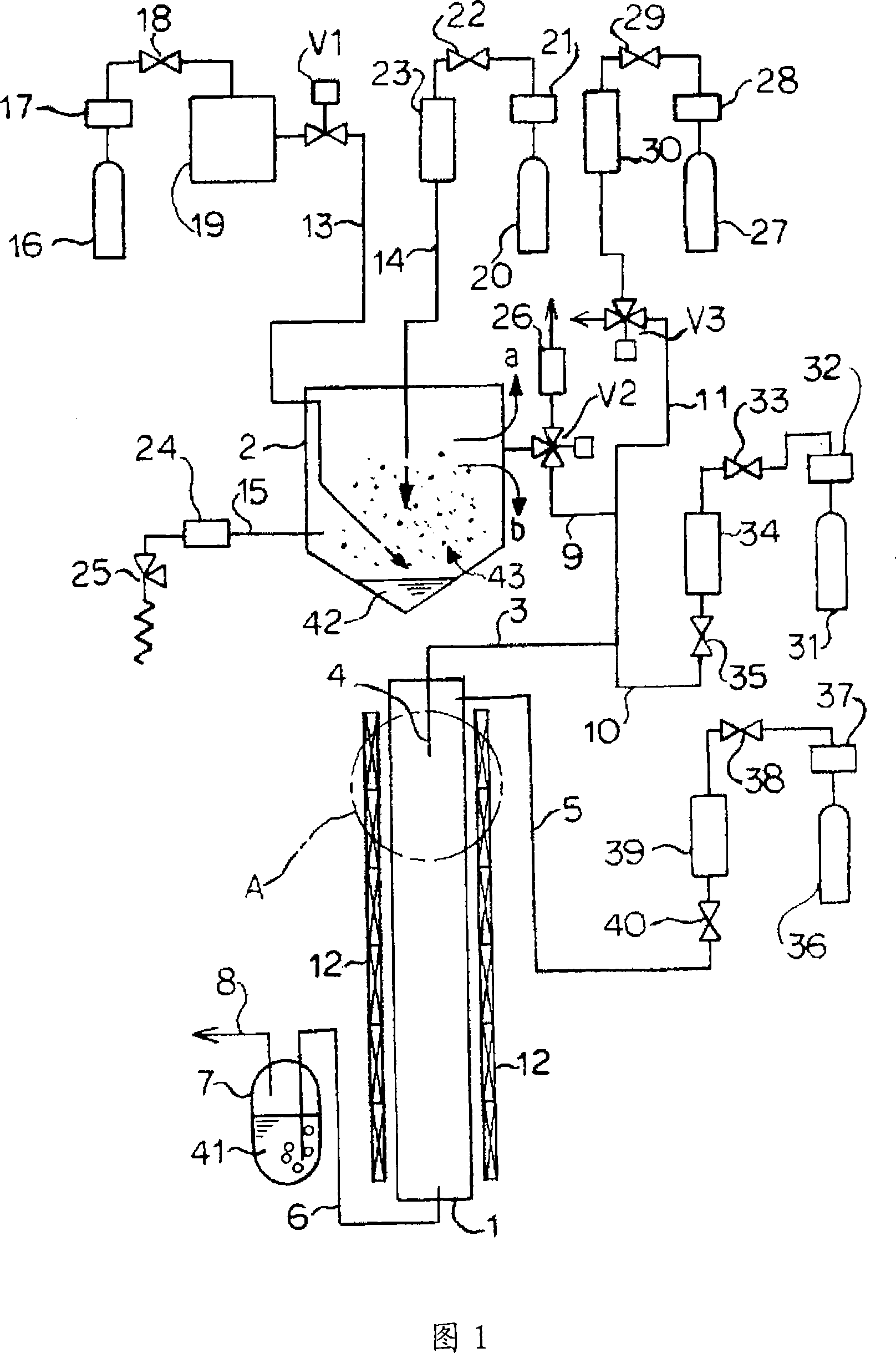
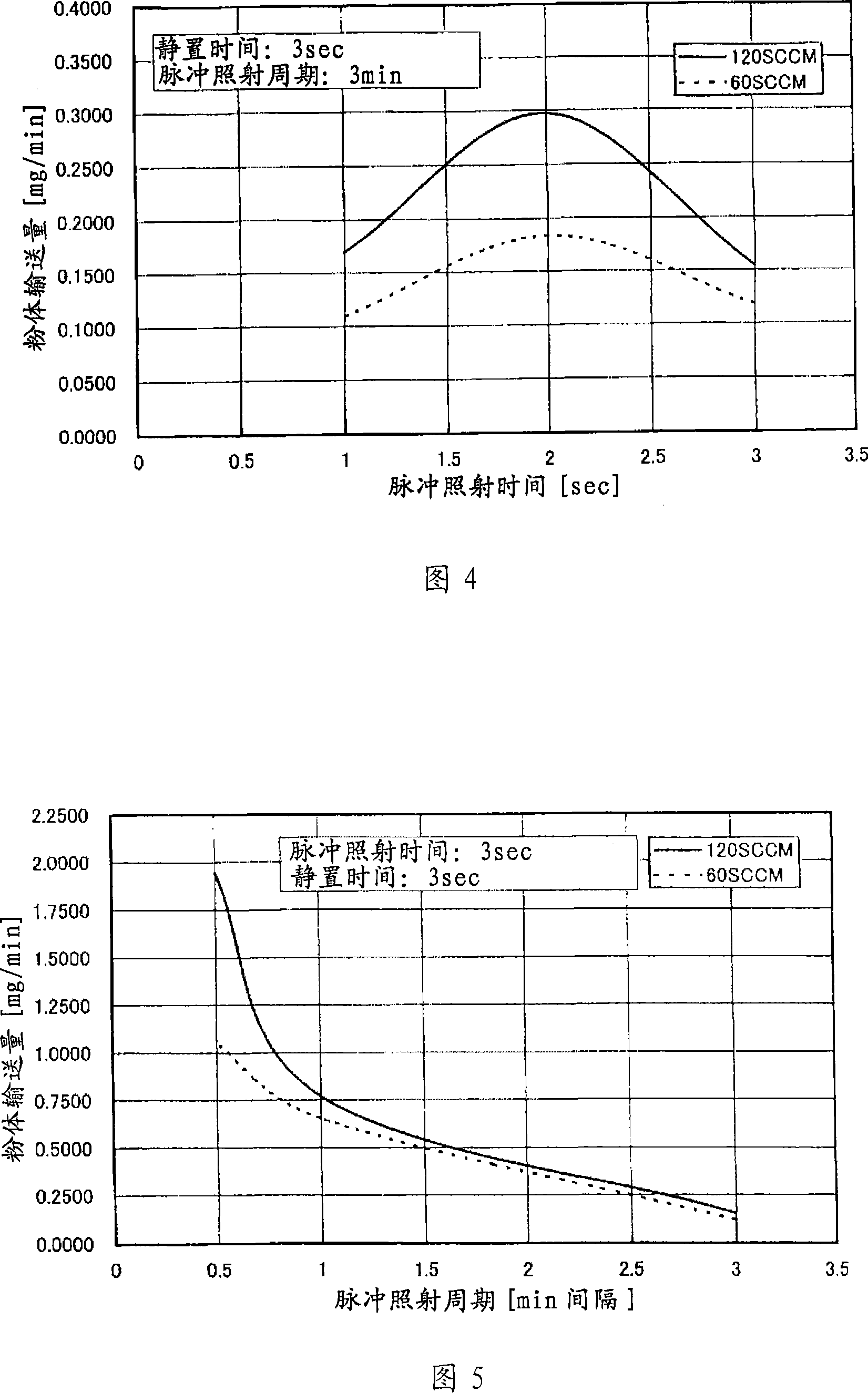
[0155] First, catalyst floatation was carried out under pulse gas generation conditions in which the electromagnetic switching valve V1 was intermittently opened and closed at 600 times / min to generate a high-pressure pulse gas of 0.3 MPa. The high-pressure pulse gas is sprayed from the front end of the high-pressure pulse gas introduction pipe 13, and the irradiation time on the catalyst in the catalyst storage tank 2 is set to 1, 2, and 3 seconds. After flotation, stop the subsequent high-pressure pulse gas irradiation, and let stand for 3 seconds. Under the above conditions of catalyst floating and standing still, when the flow rate of the carrier gas supplied from the helium cylinder 20 was 60, 120 SCCM, the delivery amount of the floating catalyst delivered to the reaction furnace 1 was measured. The measurement results are shown in Figure 4. The catalyst used is Fe-In-Sn-O.

[0156] It can be seen from the measurement results of the catalyst powder delivery amount and ...

experiment example 2

[0158] Under the condition that the pulse irradiation time is set to 3 seconds, the high-pressure pulse gas irradiation is performed and then left to stand for 3 seconds. After standing still, the actual cycle, in other words, the delivery time interval, that is, the pulse irradiation cycle time, is changed to 0.5, 1, 3 minutes (min). Other conditions are all the same as in Experimental Example 1. When the flow rate of the carrier gas of helium is set to 60, 120 SCCM, the delivery amount of the floating catalyst delivered to the reaction furnace 1 is measured, and the measurement results are shown in FIG. 5 .

[0159] It can be seen from the measurement results of catalyst powder delivery amount and pulse irradiation cycle time in Fig. 5 that the pulse irradiation cycle time of 3 minutes is appropriate.

experiment example 3

[0161] The pulse irradiation time is set to 3 seconds, and the standing time after the high-pressure pulse gas irradiation is changed to 0.5, 3, and 10 seconds. Other conditions are the same as in Experimental Example 1 and 2. The flow rate of the helium carrier gas is set to 60, At 120SCCM. The transport amount of the floating catalyst transported to the reaction furnace 1 was measured, and the measurement results are shown in FIG. 6 .

[0162] It can be seen from the measurement results of the catalyst powder delivery amount and the resting time in Fig. 6 that the resting time of 10 seconds is too long to promote the sedimentation of the catalyst, so the resting time of 3 seconds is appropriate.

[0163] Moreover, considering the use of high-pressure pulse gas, a safety valve 25 is installed at the bottom of the catalyst storage tank 2 through a gas discharge pipe 15 and a filter 24 . In addition, in the above-mentioned reaction furnace 1, a thermal decomposition method is ...


PUM

PropertyMeasurementUnit
diameteraaaaaaaaaa
diameteraaaaaaaaaa

Abstract

A process for producing a carbon nanostructure, comprising effecting contact of a raw gas with catalyst microparticles, while allowing them to flow, in a reactor furnace, wherein a high-pressure pulse gas is instantaneously blown to the catalyst microparticles to thereby float the same, then the floating of catalyst microparticles is discontinued so as to allow the catalyst microparticles to freely fall, and selection of particle diameter is carried out, and wherein catalyst microparticles having been selected in accordance with appropriate particle diameter control thus performed is transferred and fed into the reactor furnace. By this process, a carbon nanostructure can be continuously produced stably at low cost without being influenced by a dispersion of particle diameter inherent in catalyst raw materials. Further, there is provided a carbon nanostructure comprised of a curly carbon nanotube of 1 to 300 nm diameter, the curliness being one with a three-dimensional configuration having bending points irregularly incorporated therein.

Description

[0001] technology area [0002] The present invention relates to a method for producing carbon nanostructures such as carbon nanotubes and carbon nanocoils, a production device, and carbon nanostructures. Background technique [0003] Carbon nanostructures are nanoscale substances composed of carbon atoms, such as carbon nanotubes, carbon nanotubes with particles formed on carbon nanotubes, brush-like carbon nanotubes formed by a plurality of carbon nanotubes, Carbon nanotubes include twisted carbon nanohelixes (CarbonNanotwist), coil-shaped carbon nanocoils, spherical shell-shaped fullerenes, and the like. [0004] For example, in 1994, Amelinckx et al. (Amelinckx, X.B.Zhang, D.Bernaerts, X.F.Zhang, V.Ivanov and J.B.Nagy, SCIENCE, 265 (1994) 635 (Non-Patent Document 1)), using chemical vapor deposition (Chemical Vapor Deposition, hereinafter referred to as CVD method), synthesized carbon nanocoils for the first time. Furthermore, it was clarified that carbon nanocoils have ...

Claims


Application Information

Patent Timeline
Patent Type & Authority Applications(China)
IPC IPC(8): C01B31/02D01F9/127D01F9/133
CPCD01F9/133C01B31/0233C01B2202/36D01F9/127B82Y40/00B82Y30/00C01B32/162C01B32/18B82B3/0004
Inventor 中山喜万长坂岳志坂井彻后藤俊树土屋宏之盐野启祐冈崎信治
Owner JAPAN SCI & TECH CORP
Why Eureka
Try Eureka