Eureka AIR delivers breakthrough ideas for toughest innovation challenges, trusted by R&D personnel around the world.

Bridge type grating light modulator and array thereof

A light modulator and bridge-type technology, applied in the direction of instruments, optics, optical components, etc., can solve the problems of low effective diffraction area of ​​GLV and difficult integration into area array, etc., and achieve fast modulation speed, high light extraction efficiency, and high yield rate Effect

Inactive Publication Date: 2010-03-24
CHONGQING UNIV
View PDF2 Cites 0 Cited by
  • Summary
  • Abstract
  • Description
  • Claims
  • Application Information

AI Technical Summary

Problems solved by technology

[0008] In order to overcome the disadvantages of complex DMD technology and the disadvantages of low effective diffraction area of ​​GLV and difficulty in integrating into an area array, the purpose of the present invention is to provide a bridge grating light modulator, which adopts the principle of diffraction to perform phase modulation on incident light, increasing the Effective use of large device area, improved optical efficiency and contrast, and simplified manufacturing process

Method used


Image

  • Bridge type grating light modulator and array thereof
  • Bridge type grating light modulator and array thereof
  • Bridge type grating light modulator and array thereof

Examples


Embodiment Construction

[0027] Below in conjunction with accompanying drawing and embodiment the present invention is further described:

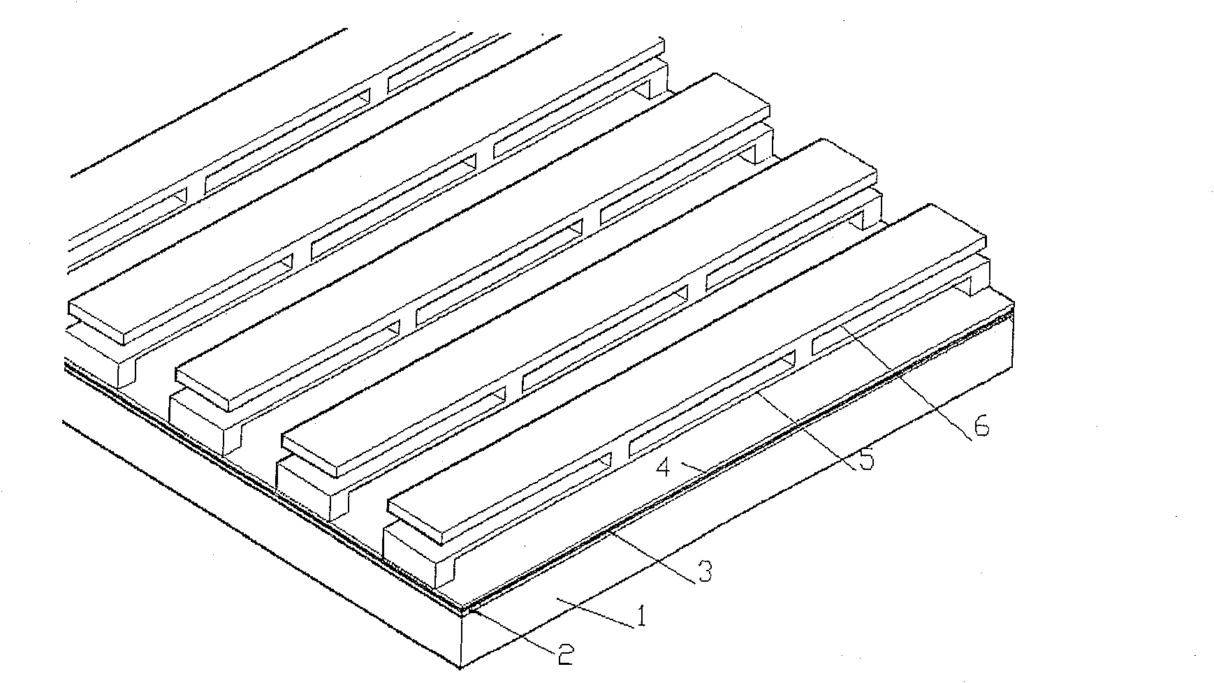
[0028] Figure 1a A side view of the structure of the single-pixel bridge grating light modulator of the present invention is shown. Among them, a layer of oxide layer 2 is formed on the silicon substrate 1 through thermal oxidation; then sputtering (or vapor deposition) and patterning the bottom reflective surface 3; and then depositing a transparent insulating layer 4 on the bottom reflective surface 3; The insulating layer 4 is spin-coated with a sacrificial layer to etch the supporting pillars; then sputtering (or evaporation) bridge elastic beams 5; by depositing a second layer of sacrificial layer and sputtering (or evaporation) processes, the top reflection layer is formed Surface 6, and then etch the required grating on it, which is the upper electrode; finally release the sacrificial layer to obtain the structure shown in Figure 1. The incident light is ...


PUM


Abstract

The invention discloses a bridge-typed light modulator which can carry out phase modulation for incidence lights and an array thereof, the modulator is a device which is constructed on a silicon slicein a laminated way, based on MOEMS technology. An elastic beam with two ends supported is right above an under layer reflecting surface, on the elastic beam, two anchor points support a metallic reflection grizzly bar to form a top layer reflecting surface. The space between the top layer reflecting surface and the under layer reflecting surface is variable and is n*lambda / 2 when no voltage is applied between the two surfaces; when fixed bias voltage V1 is applied, the space is (2n-1)*lambda / 4; when the range of applied voltage is between 0 and V1, the space is linearly adjustable between n*lambda / 2 and (2n-1)*lambda / 4. When a plurality of the light modulators are used for forming the array, bias voltage can be applied by each light modulator independently, and the top layer reflecting surface does vertical translation to form lattices of different diffraction effects, thus leading to no clearance of pixel projection imaging in grating direction and achieving the effect of seamless display. The light modulator can be widely used for display, projection, printing, optical communication and spectrometers.

Description

technical field [0001] The present invention relates to a light modulation device, more specifically, the present invention relates to a bridge grating light modulator, the device uses a rectangular groove grating with variable depth to modulate the phase of incident light. Background technique [0002] With the development of digital technology, large-screen display, especially the maturity of high-definition digital TV technology, many designers and inventors have managed to develop optical modulators that can be used alone or with other modulators, which are based on MOEMS technology The manufactured optical modulators have achieved high-speed development and wide application due to their excellent performance. When they are applied to display devices, they have common advantages, that is, high light extraction efficiency, high definition, fast modulation speed, more gray levels, compatible with digital TV technical indicators, and excellent contrast, brightness and unifo...

Claims


Application Information

Patent Timeline
Patent Type & Authority Patents(China)
IPC IPC(8): G02B26/08
Inventor 张智海金珠张洁王宁韦玮
Owner CHONGQING UNIV
Why Eureka
Eureka Blog
Learn More