
Electric connecting structure of circuit board embedding with semiconductor chip

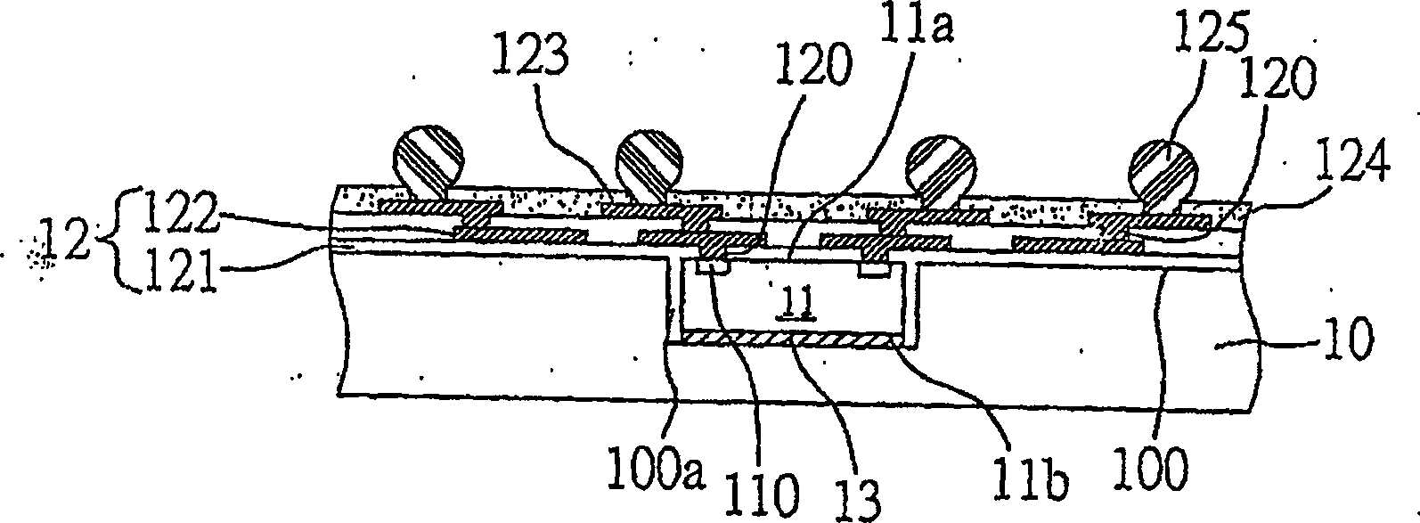
A semiconductor and circuit board technology, applied in semiconductor devices, semiconductor/solid-state device parts, circuits, etc., can solve problems such as thermal stress mismatch, inability to meet thin lines, separation of electrode pad surfaces, etc., to solve the problem of difficult matching of thermal expansion coefficients , avoid the effect of separation of layer build-up lines and reduction of electrical quality

Active Publication Date: 2009-09-09
PHOENIX PRECISION TECH CORP
View PDF2 Cites 0 Cited by
  • Summary
  • Abstract
  • Description
  • Claims
  • Application Information

AI Technical Summary

Problems solved by technology

However, due to the mismatch of thermal expansion coefficients (Coeffecient Thermal Efficent; CTE) of the components around the formed conductive blind vias (such as insulating layer, protective layer on the surface of the semiconductor chip, etc.), the formed semiconductor package is due to various components The difference in thermal expansion between components will cause thermal stress in the semiconductor package, which may cause the formed circuit structure to separate from the electrode pad surface of the semiconductor chip, resulting in electrical failure of the product
[0009] In the existing semiconductor package, in order to meet the requirements of the fine pitch and the short signal conduction path, the conductive blind holes connected to the circuit adopt a stacked structure. However, due to the components around the conductive blind holes, For example, the thermal expansion coefficients of the insulating layer and the protective layer on the surface of the semiconductor chip are different, resulting in a mismatch of thermal stress generated inside the product, and the separation between the electrode pad and the circuit structure of the semiconductor chip, so it cannot meet the requirements of thin lines. Requirements, but also affect the reliability of the product

Method used


Image

  • Electric connecting structure of circuit board embedding with semiconductor chip
  • Electric connecting structure of circuit board embedding with semiconductor chip
  • Electric connecting structure of circuit board embedding with semiconductor chip

Examples


no. 1 example

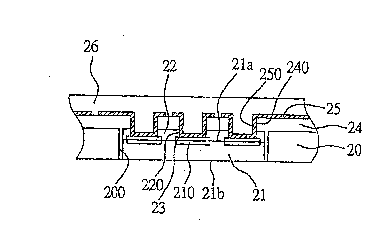
[0054] like figure 2 Shown is a schematic cross-sectional view of the first embodiment of the circuit board structure for embedding semiconductor chips of the present invention. As shown in the figure, the circuit board structure of the embedded semiconductor chip of the present invention includes: a support plate 20, at least one semiconductor chip 21, core surface protection layer 22, metal layer 23, dielectric layer 24, circuit layer 25 and hollow conductive Blind hole 250.

[0055] The support board 20 mentioned above can be a circuit board, an insulating board, or a core board, and the material of the core board can be metal or non-metal. In addition, at least one opening 200 is formed in the support plate 20 for accommodating the semiconductor chip 21 .

[0056] The semiconductor chip 21 has an active surface 21a and an opposite passive surface 21b, and a plurality of electrode pads 210 are formed on the active surface 21a.

[0057] The core protection layer 22 is fo...

no. 2 example

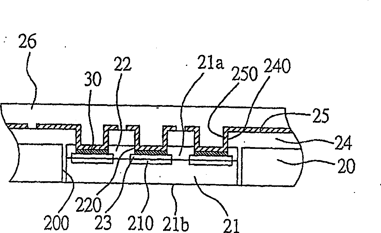
[0064] like image 3 Shown is a schematic cross-sectional view of the second embodiment of the circuit board structure for embedding semiconductor chips of the present invention.

[0065] The structure of the circuit board embedded with semiconductor chips in this embodiment is substantially the same as that of the first embodiment, the main difference is that this embodiment further includes a buffer metal layer.

[0066] like image 3 As shown, a buffer metal layer 30 is formed between the above-mentioned hollow conductive blind hole 250 and the metal layer 23, and the buffer metal layer 30 can be copper foil, so that when the thickness of the metal layer 23 is insufficient, the thickened The buffer metal layer 30 is used as a blocking layer for subsequent laser drilling of the dielectric layer 24 to form holes (ie, blind holes), thereby preventing the electrode pads 210 of the semiconductor chip 21 covered thereunder from being damaged.

no. 3 example

[0068] like Figure 4 Shown is a schematic cross-sectional view of a third embodiment of the circuit board structure for embedding semiconductor chips of the present invention.

[0069] In this embodiment, the structure of the circuit board for embedding semiconductor chips is roughly the same as that of the aforementioned first embodiment. The circuit build-up structure 40 on the surface of 25 .

[0070] The circuit build-up structure 40 includes at least one dielectric layer 400, a circuit layer 402 stacked on the surface of the dielectric layer 400, and a full circuit layer 402 formed in the dielectric layer 400 for electrically connecting the circuit layer 402 to the circuit layer 25. The metal-plated blind hole 404 ; of course, a hollow conductive blind hole (not shown) can also be used as a telecommunication conduction path between the circuit layer 402 and the circuit layer 25 .

[0071] The dielectric layer 400 fills the hollow conductive via 250 . In this embodimen...


PUM


Abstract

The invention provides a circuit board structure for embedding semiconductor chip, in which at least half of the semiconductor chip is contained in an opening of a supporting board, a dielectric layer and a circuit layer are formed on the supporting board and the semiconductor chip, and a hollow conductive blind hole is formed in the dielectric layer to electrically connect the circuit layer and the semiconductor chip. By employing the hollow conductive blind hole of the present invention, separation due to thermal stress generated by different expansion coefficient is avoided in preparation, thereby ensuring electric function of products.

Description

technical field [0001] The invention relates to a circuit board structure for embedding a semiconductor chip, in particular to a hollow conductive blind hole structure for electrically connecting the semiconductor chip embedded in a supporting board and a circuit. Background technique [0002] With the development of semiconductor packaging technology, different packaging types have been developed for semiconductor devices, which mainly install semiconductor chips on a package substrate or lead frame first, and then electrically connect the semiconductor chips On the packaging substrate or lead frame, encapsulation is then performed with glue. Among them, ball grid array (Ball grid array, BGA) is an advanced semiconductor packaging technology. Place a plurality of solder balls arranged in a grid array, so that more input / output connection terminals (I / Oconnection) can be accommodated on the semiconductor chip carrier of the same unit area to meet the requirements of highly ...

Claims


Application Information

Patent Timeline
Patent Type & Authority Patents(China)
IPC IPC(8): H01L23/488H05K1/18
CPCH01L2924/0002H01L24/19H01L2224/04105H01L2224/12105H01L2224/19H01L2224/73267H01L2924/15153H01L2924/18162H01L2924/351H01L2924/00H01L2924/00012
Inventor 许诗滨连仲城陈尚玮
Owner PHOENIX PRECISION TECH CORP
Learn More