
Digital phase locked loop

A digital phase-locked loop, digital technology, applied in angle demodulation through phase difference detection, automatic power control, electrical components, etc., can solve the problems of PLL instability, error, low signal strength, etc., to reduce error sensitivity Effect

Inactive Publication Date: 2009-08-26
NXP BV
View PDF4 Cites 0 Cited by
  • Summary
  • Abstract
  • Description
  • Claims
  • Application Information

AI Technical Summary

Problems solved by technology

[0006] However, common IF demodulators have proven to be unstable in daily operation, in particular because of low signal strength, unwanted FM / PM modulation, poor signal Noise ratio and static carrier frequency error
Therefore, the conclusion is that the traditional PLL may be unstable or not provide any stable demodulation results

Method used


Image

  • Digital phase locked loop
  • Digital phase locked loop

Examples


Embodiment Construction

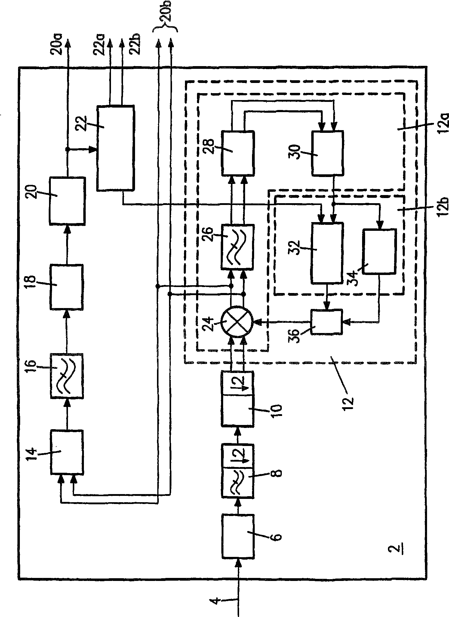
[0025] figure 1 A demodulator 2 of an intermediate frequency signal 4 for a tuner of a television signal receiver (not shown) is shown. The demodulator 2 includes an analog / digital converter 6 , a decimation filter 8 , a Hilbert filter 10 and a digital phase-locked loop (PLL) 12 . Digital Nyquist filter 14, low pass filter 16, all pass filter 18, sign detector 20 and gain control circuit 22 and video output 20a, audio output 20b, tuner control output 22b and IF amplifier control output 22a Both are also set in demodulator 2.

[0026] Digital PLL 12 includes rotationally operating coordinate rotating digital computer 24, low pass filter 26, carrier monitor circuit 28 and linearly operating coordinate rotating digital computer 30, which together form phase detector 12a. The loop filter block 12b consists of a low pass filter 32 with adjustable bandwidth and a frequency locked loop (FLL) 34 . Digital PLL 12 also includes digitally controlled oscillator (DCO) 36 .

[0027]The ...


PUM


Abstract

The invention relates to a digital phase locked loop (PLL) 12 for demodulating an intermediate frequency signal. The digital phase locked loop12 comprises two coordinate rotation digital computers 24 and 30 in its phase detector. The robustness of the PLL 12 can be improved by means of a gain control circuit 27, a sign detector 20, a carrier monitoring circuit 28 and an adjustable loop filter 32.

Description

technical field [0001] The present invention relates to a digital phase-locked loop (PLL) for demodulating amplitude modulated signals, and more particularly, the invention relates to a phase-locked loop for an intermediate frequency modulator for a broadcast signal, such as a television signal, which has a digital phase comparison A circuit, a digital loop filter and a digital controllable oscillator, the phase comparison circuit includes a digital mixer and a phase shift circuit. Background technique [0002] Common digital phase-locked loops are often used to demodulate modulated signals, in which case the transmitted information signal is demodulated from the modulated carrier signal by means of a PLL. Broadcast signals, especially television signals, are often modulated by AM. Accordingly, PLLs are used in receiver circuits in order to identify information-carrying signals from AM-IF by means of synchronous demodulation using carrier regeneration. [0003] The digital...

Claims


Application Information

Patent Timeline
Patent Type & Authority Patents(China)
IPC IPC(8): H03D3/24H03D1/22H03L7/085H04L27/06
CPCH03D1/2254
Inventor H·-J·科赫恩M·祖普克
Owner NXP BV
Learn More