
Method and apparatus for video signal processing

a video signal and processing method technology, applied in the field of video signal processing, can solve the problems of substantial loss of coding efficiency, and high sensitivity to bit errors, and achieve the effects of improving backward compatibility, facilitating the introduction of video signal processors, and increasing error rates

Active Publication Date: 2012-02-07
GOOGLE TECH HLDG LLC
View PDF24 Cites 0 Cited by
  • Summary
  • Abstract
  • Description
  • Claims
  • Application Information

AI Technical Summary

Benefits of technology

The invention is a video signal processor that improves video quality in a video system by reducing errors and improving error resilience. It achieves this by generating a combined video data by combining a first encoded video signal and error redundancy data for a second encoded video signal. The error redundancy data is generated by error encoding the second video signal and detecting errors in the data. This allows for improved video quality in the presence of errors and better trade-off between error performance and data rate. The video signal processor can be used as a pre-processor for a video decoder, providing improved backwards compatibility and facilitating introduction to existing systems. It can efficiently generate output video data with improved video quality.

Problems solved by technology

However, a problem with most standardized video codecs is that they are very sensitive to bit errors e.g. occurring during the broadcasting, distribution and retrieval etc of the encoded video signal.
Also, the use of variable length codes for encoding video data results in a high sensitivity to bit errors.
Unfortunately, such error resilience schemes all introduce substantial amounts of additional error data thereby resulting in a substantial loss in coding efficiency for situations where the error characteristics are better than the scenario for which the coding is designed (e.g. when the video signal is transmitted over an error free channel).
However, if such an uncoded video signal needs to be transmitted over an error prone channel, then adding all but the simplest of the error resilience features requires decoding and re-encoding of the video signal which is a computationally intensive task.
However, the use of forward error correcting coding usually requires the error characteristics of the channel to be well known in advance of the transmission or requires that a worst case scenario is assumed thereby resulting in a higher error correcting data rate and reduced coding efficiency.
Furthermore, as the error performance of error correcting codes tend to degrade steeply if the error rate increases beyond the level for which the code was designed, a substantial margin must typically be included.
In particular, as error correcting codes tend to not degrade smoothly and gradually, it must be ensured that the system works with a data rate which ensures that the operating point never or very rarely reaches the situation where the coding performance is being degraded.
Furthermore, although the use of re-transmission techniques may be suitable for some systems, it is not practical for other systems.
For example, re-transmission is unsuitable for some non-real time systems such as distribution of video signals by DVDs.
Also, the use of retransmissions does not scale well if multiple users are receiving the same content as the retransmission resource requirement may quickly exceed the initial broadcasting resource.

Method used


Image

  • Method and apparatus for video signal processing
  • Method and apparatus for video signal processing
  • Method and apparatus for video signal processing

Examples


Embodiment Construction

[0038]The following description focuses on embodiments of the invention applicable to a distribution system for a video signal and in particular to a distribution system wherein an MPEG-2 encoded video bitstream is transmitted through a communication channel introducing communication errors to the transmitted bitstream. The system does not use any retransmission techniques and may specifically be a broadcasting system. It will be appreciated that the invention is not limited to this application but may be applied to many other systems.

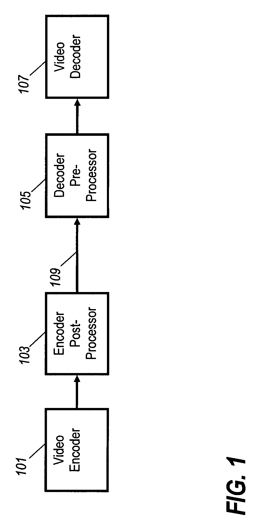
[0039]FIG. 1 illustrates a video signal distribution system in accordance with some embodiments of the invention.

[0040]The video signal distribution system comprises a video encoder 101 which encodes a video signal in accordance with a suitable video encoding algorithm. In the specific example, the video encoder 101 is an MPEG-2 video encoder generating MPEG-2 video data in the form of a video bitstream.

[0041]The video encoder 101 is coupled to an enco...


PUM


Abstract

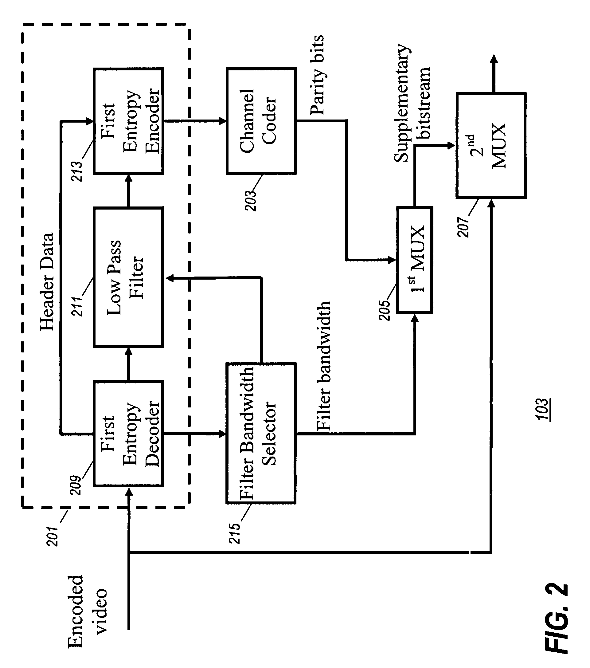
A first video signal processor (103) receives a first encoded video signal from which a video unit (201) generates a second encoded video signal, where the second encoded video signal is a reduced data rate version of the first encoded video signal. An error encoder (203) generates error redundancy data for the second encoded video signal and a multiplexer (207) generates output video data comprising the first encoded video signal and the error correcting data but not comprising the second encoded video signal. A second video processor (105) receives the output video data and a video unit (303) regenerates the second video signal from the first video signal. An error unit (305) detects errors for at least a first segment of the second video signal in response to the error redundancy data. A combiner (307) then generates combined video data by combining corresponding segments of the first encoded video signal and the second encoded video signal.

Description

FIELD OF THE INVENTION[0001]The invention relates to video signal processing and in particular, but not exclusively, to improving error resilience for broadcast distributed video signals.BACKGROUND OF THE INVENTION[0002]Transmission and distribution of video signals is increasingly performed using digitally encoded video signals. For example, digital terrestrial and satellite television broadcasting is gradually taking over from analogue broadcasting systems. Also, digital video signal is used for distribution via e.g. the internet or using magneto optical carriers such as Digital Versatile Discs etc.[0003]In order to maintain manageable data rates and file sizes for digital video, complex video encoding and decoding algorithms are used that provide a very high degree of compression. Examples of popular standardized video codecs are the Motion Picture Expert Group's MPEG-2 and MPEG-4 Technical Standards.[0004]However, a problem with most standardized video codecs is that they are ve...

Claims


Application Information

Patent Timeline
Patent Type & Authority Patents(United States)
IPC IPC(8): H04B1/66H04N11/04H04N11/02H04N7/12
CPCH04N21/23424H04N19/67H04N21/235H04N21/435H04N21/44016H04N21/44209H04N21/4425H04N21/6125H04N19/46H04N19/61H04N19/164H04N19/174H04N19/17H04N19/48H04N19/80H04N19/85H04N21/234327
Inventor MAY, ANTHONY R.ISHTIAQ, FAISALSHANABLEH, TAMER
Owner GOOGLE TECH HLDG LLC
Learn More