
Ion injection uniformity control system and control method

An ion implantation and control system technology, which is applied in semiconductor/solid-state device manufacturing, discharge tubes, electrical components, etc., can solve problems such as the inability to meet the requirements of the semiconductor doping process of micro-nano devices, and achieve automatic adjustment of dose uniformity control. Effect

Inactive Publication Date: 2009-08-05
BEIJING ZHONGKEXIN ELECTRONICS EQUIP
View PDF5 Cites 0 Cited by
  • Summary
  • Abstract
  • Description
  • Claims
  • Application Information

AI Technical Summary

Problems solved by technology

[0003] At present, the control of the traditional ion implanter in China is still in a semi-automatic state, and the dose uniformity control of ion implantation doping is a blank, which cannot meet the requirements of semiconductor doping technology in the manufacture of micro-nano devices

Method used


Image

  • Ion injection uniformity control system and control method
  • Ion injection uniformity control system and control method
  • Ion injection uniformity control system and control method

Examples


Embodiment

[0045] Record a set of horizontal uniformity correction data according to the above method, as shown in Table 1 below:

[0046] Table 1: Unit: microampere

[0047] Correction

[0048] The number of corrections in Table 1 refers to the calculation formula for scanning voltage waveform correction

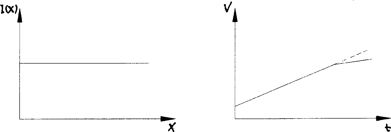
[0049] [dV(x) / dt] n =[dV(x) / dt] 0 ×I(x) / I 0 The number of corrections is taken as 3 times, and the scanning voltage waveform is not corrected at 0 times, which is a linear scanning waveform. I(x) is the beam current distribution value measured along the X direction under the corresponding scanning voltage, and 10 points are measured from left to right in the range of 200mm. It can be seen from the table that the scanning voltage waveform generally passes through 2-3 After one calibration, the horizontal uniformity can reach ±0.5%.

[0050] Vertical uniformity correction data, the test data is shown in Table 2 below:

[0051] Table 2: Unit: 10 14 Particle count / cm ...


PUM


Abstract

The invention discloses an ion implantation uniformity control system and a control method, relates to an ion implanter and belongs to the field of semiconductor manufacturing. The system includes a moving Faraday cup, a dose integration detector, a digitally controlled scanning generator, a target stage motion and uniformity controller and a computer, and the output of the moving Faraday cup is connected with the dose integration detector; the output of the dose integration detector is It is connected with the target stage motion and uniformity controller; the moving Faraday cup, dose integration detector, numerical control scan generator, target stage motion and uniformity controller are all connected with the computer, and the computer coordinates and controls the action; the uniformity The uniformity control method includes a horizontal uniformity detection and correction method and a vertical uniformity detection and correction method, both of which make the uniformity reach the error range by detecting the scanning data and correcting the data multiple times. The invention can automatically realize accurate detection, automatic adjustment and dose uniformity control of ion implantation dose.

Description

technical field [0001] The invention relates to an ion implantation uniformity control system and a control method, in particular to an ion implanter and belongs to the field of semiconductor device manufacturing. Background technique [0002] Ion beam implanter is one of the most critical doping equipment in the manufacture of semiconductor devices. As the integration of semiconductor device manufacturing develops towards the system-on-chip scale, the wafer used for device manufacturing expands toward a size of more than 300mm, while the size of unit devices shrinks toward micro-nano thin lines, especially the size of on-chip transistors and field effect transistors. The shrinkage of ion beam implantation poses obvious challenges to the ion beam implantation doping technology. For 100nm-level devices, the unit field effect transistor needs to generate a shallow junction source-drain structure, that is, the source-drain junction depth becomes very shallow, and the source-dr...

Claims


Application Information

Patent Timeline
Patent Type & Authority Patents(China)
IPC IPC(8): H01L21/265H01J37/317
Inventor 唐景庭伍三忠郭建辉邱小莎王迪平刘仁杰孙勇
Owner BEIJING ZHONGKEXIN ELECTRONICS EQUIP
Learn More