Light-emitting device and electronic device
A technology of light-emitting devices and light-emitting elements, which is applied in the direction of light-emitting materials, electric solid-state devices, semiconductor devices, etc., and can solve the problems of high added value and difficulty in balancing
- Summary
- Abstract
- Description
- Claims
- Application Information
AI Technical Summary
Problems solved by technology
Method used
Image
Examples
Embodiment 1
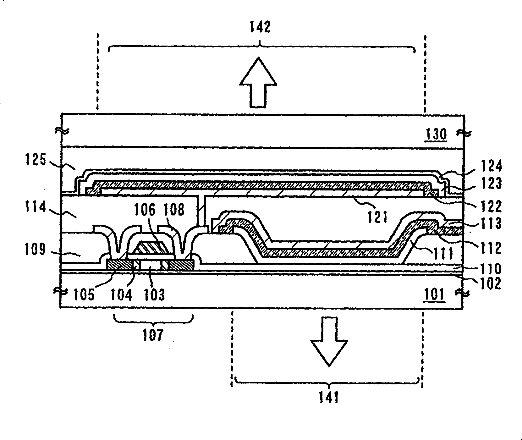
[0124] This example will use Figure 4A-Figure 7 The manufacturing process of the light-emitting element having the structure of Embodiment Mode 1 will be described.
[0125] Figure 4A and 4B represents a process of forming a first electrode of a first light-emitting element and a part of a TFT of a second light-emitting element, Figure 4A represents its top view, Figure 4B means along Figure 4A Sectional view of the A-A' line cut.
[0126] Such as Figure 4A As shown, an underlying insulating film 402 is formed on a glass substrate (first substrate 401). In this embodiment, the base insulating film has a two-layer structure, using SiH 4 , NH 3 , N 2 O is used as a reactive gas to form the first silicon oxynitride film with a thickness of 50-100nm; using SiH 4 , N 2 O is used as a reactive gas to form a second silicon oxynitride film with a thickness of 100-150 nm, and after stacking, a two-layer stack is formed.
[0127] Then, an amorphous silicon film is lami...
Embodiment 2
[0149] This embodiment will describe a structural example in which a light emitting device including at least a pixel portion, a driving circuit for driving a pixel, and a pixel processing circuit is formed on a substrate with an insulating surface, and an operation method for reducing power consumption.
[0150] Figure 11 Shown is an example of a system in which a display portion is formed on a glass substrate, on which a pixel portion 801, a source line driver circuit 802, a gate line driver circuit 803, three image processing circuits 804- 806, memory 807, interface circuit 808, power supply timing control circuit 809.
[0151] Figure 11 In the block diagram shown, a pixel portion 801 is a portion that displays an image; a source line driver circuit 802 and a gate line driver circuit 803 are driver circuits that drive pixels. Pixel data is input to the source line driver circuit 802 . In addition, the interface circuit 808 inputs external image data or image-based data...
Embodiment 3
[0160] An electronic device including the light-emitting device formed according to Embodiment Modes 1 to 5, Examples 1 and 2 will be described in this example. Typical examples include camcorders, digital cameras, notebook computers, portable information terminals (such as portable computers, mobile phones, portable game consoles or e-books), playback devices including recording media (specifically, devices capable of processing such as digital data on a recording medium such as a general-purpose disc (DVD) and has a display capable of displaying data images), television receivers, electronic bulletin boards, cash registers, etc. This embodiment shows an example in which the light-emitting device of the present invention is applied to a mobile phone.
[0161] 9A to 9D show the external view of the mobile phone of the present invention, FIG. 9A shows an oblique perspective view of an open state, and FIG. 9B shows an oblique perspective view of a folded state, which is also see...
PUM
 Abstract
Description
Claims
Application Information
 - R&D
- Intellectual Property
- Life Sciences
- Materials
- Tech Scout
- Unparalleled Data Quality
- Higher Quality Content
- 60% Fewer Hallucinations
Browse by: Latest US Patents, China's latest patents, Technical Efficacy Thesaurus, Application Domain, Technology Topic, Popular Technical Reports.
© 2025 PatSnap. All rights reserved.Legal|Privacy policy|Modern Slavery Act Transparency Statement|Sitemap|About US| Contact US: help@patsnap.com


