
Pulse width modulation circuit controlling output current of an inverter circuit for motor-driven blower or electric vacuum cleaner

a technology of inverter circuit and output current, which is applied in the direction of motor/generator/converter stopper, dynamo-electric converter control, stopping arrangement, etc., can solve the problems of excessive current flow, increase the pulse width, and easily limit or suppress an inrush, etc.

Inactive Publication Date: 2008-04-22
TOSHIBA TEC KK
View PDF13 Cites 7 Cited by
  • Summary
  • Abstract
  • Description
  • Claims
  • Application Information

AI Technical Summary

Benefits of technology

[0009]An object of the present invention is to provide means easy to be implemented as means for PWM-controlling a current to be supplied to an electric motor so as to decrease upon startup of the electric motor, and provide means which reduces an inrush current (overshoot current) at the startup of the electric motor, particularly reduces an on-startup inrush current, which is suitable for an application like a motor-driven blower.
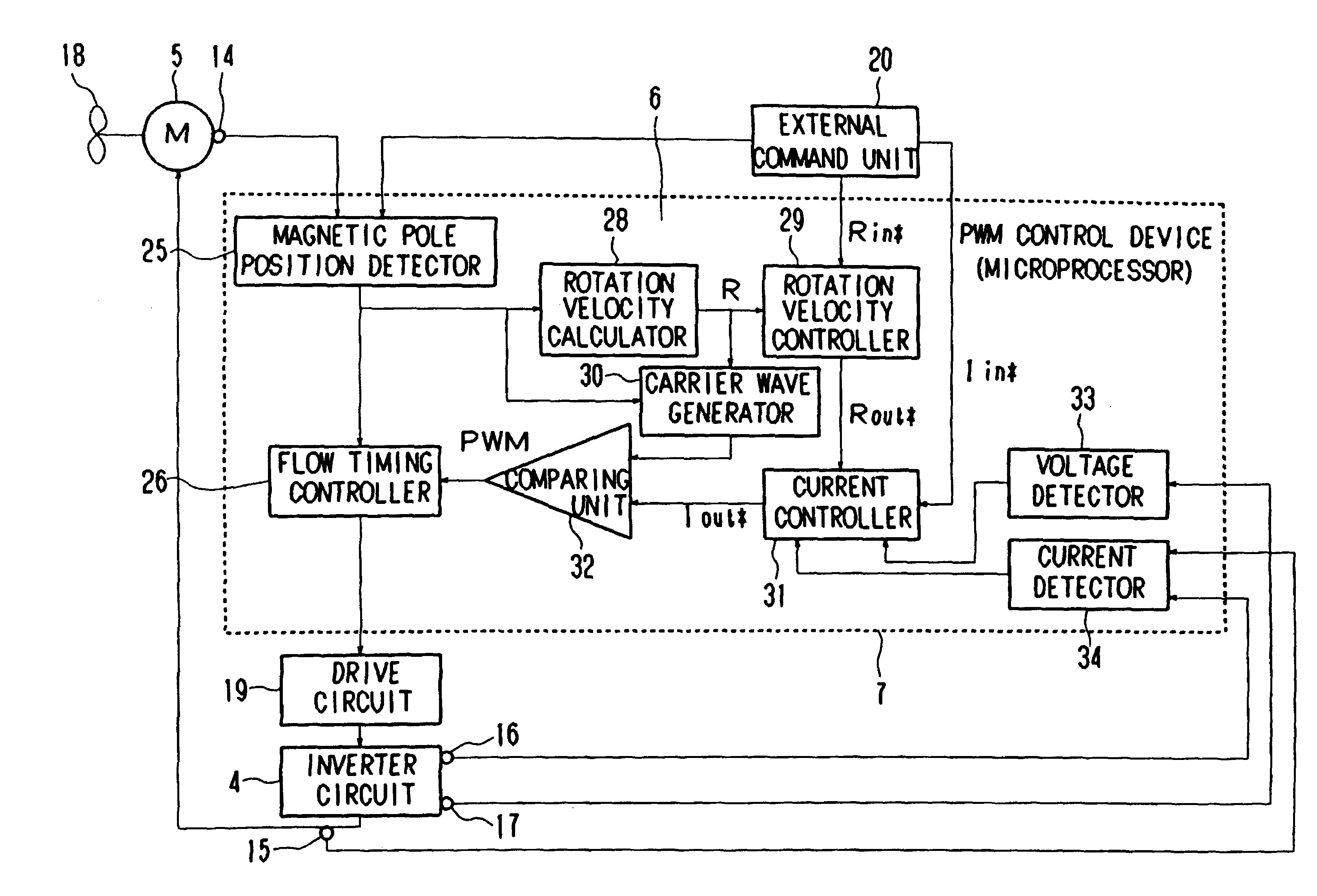
[0011]The present invention provides a PWM control device wherein a microprocessor determines a pulse width of a PWM signal through the use of a signal detected by rotation position detecting means which detects the rotational position of a rotor of a brushless motor, with respect to the amount of each current supplied from an inverter circuit for driving the brushless motor to the brushless motor to thereby perform PWM control. Under the PWM control, the microprocessor enlarges the pulse width of the PWM signal during an interrupt processing or process including a process for detecting the rotational position by the rotation position detecting means upon startup of the brushless motor and gradually enlarges the pulse width of the PWM signal according to the repetition of the interrupt processing, thereby making it possible to easily limit or suppress an inrush or overshoot current with respect to each current supplied to the motor upon startup of the motor.
[0012]The present invention according to the another aspect provides a motor-driven blower which includes a brushless motor, an air blower rotatably driven by the brushless motor, an inverter circuit which drives the brushless motor, rotation position detecting means which detects a rotational position of rotor of the brushless motor, and a PWM control device wherein a microprocessor determines a pulse width of a PWM signal through the use of a signal detected by the rotation position detecting means, with respect to the amount of each current supplied from the inverter circuit to the brushless motor to thereby perform PWM control. Under the PWM control, the microprocessor enlarges the pulse width of the PWM signal during interrupt processing including a process for detecting the rotational position by the rotation position detecting means upon startup of the brushless motor and gradually enlarges the pulse width of the PWM signal according to the repetition of the interrupt processing, thereby making it possible to easily limit or suppress an inrush or overshoot current with respect to each current supplied to the motor upon startup of the motor.
[0013]The present invention according to a further aspect provides a cleaner comprising a brushless motor, an air blower rotatably driven by the brushless motor, an inverter circuit which drives the brushless motor, rotation position detecting means which detects a rotational position of rotor of the brushless motor, and a PWM control device wherein a microprocessor determines a pulse width of a PWM signal through the use of a signal detected by the rotation position detecting means, with respect to the amount of each current supplied from the inverter circuit to the brushless motor to thereby perform PWM control. Under the PWM control, the microprocessor enlarges the pulse width of the PWM signal during interrupt processing including a process for detecting the rotational position by the rotation position detecting means upon startup of the brushless motor and gradually enlarges the pulse width of the PWM signal according to the repetition of the interrupt processing, thereby making it possible to easily limit or suppress an inrush or overshoot current with respect to each current supplied to the motor upon startup of the motor.

Problems solved by technology

On the other hand, when the brushless motor is overloaded continuously or the motor-driven blower is brought into a locked state, an excessive current continues to flow.
According to such means, however, a large current will flow upon the startup of the motor-driven blower while the time is exactly short, thus applying a load to each of electronic parts on an electric circuit.
However, Unexamined Patent Publication No.

Method used


Image

  • Pulse width modulation circuit controlling output current of an inverter circuit for motor-driven blower or electric vacuum cleaner
  • Pulse width modulation circuit controlling output current of an inverter circuit for motor-driven blower or electric vacuum cleaner
  • Pulse width modulation circuit controlling output current of an inverter circuit for motor-driven blower or electric vacuum cleaner

Examples


Embodiment Construction

[0026]One embodiment of the present invention will be described.

[0027]A motor-driven blower illustrating an embodiment of the present invention will first be described.

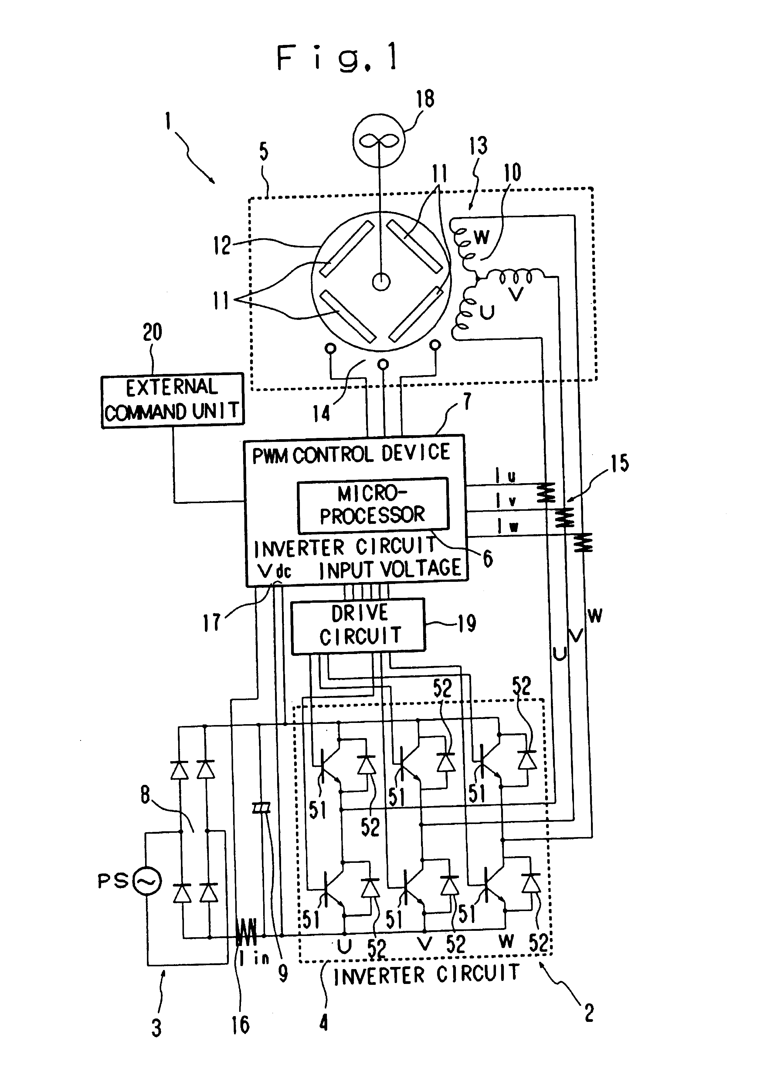
[0028]FIG. 1 is a circuit diagram showing a drive control circuit 2 of the motor-driven blower 1. The drive control circuit 2 is a device which rotatably drives a brushless motor 5 of the motor-driven blower 1 in response to a high-frequency current generated from an inverter circuit 4 high-frequency driven with a power source 3 as a drive source. The drive control circuit 2 drives and controls the inverter circuit 4 under a PWM control device 7 for performing PWM (Pulse Width Modulation) control using a microprocessor 6. The details of the respective parts or components of the drive control circuit 2 will be explained below.

[0029]The power source 3 converts an AC voltage generated from a commercial AC power supply PS to a DC voltage under rectifying / smoothing effects of a rectifier circuit 8 and a smoothing condenser...


PUM


Abstract

The present invention provides a PWM control device wherein a microprocessor detects the rotational position of rotor of a brushless motor with respect to the amount of each current supplied from an inverter circuit for driving the brushless motor to the brushless motor and outputting of a PWM signal through the use of its detected signal to thereby perform PWM control. Upon startup of the brushless motor under the PWM control, the pulse width of the PWM signal is enlarged during interrupt processing including a process for detecting the rotational position of rotor of the brushless motor, and the pulse width of the PWM signal is progressively enlarged according to the repetition of the interrupt processing. It is thus possible to easily suppress an overshoot current with respect to the current supplied to the motor upon startup of the motor.

Description

CROSS REFERENCE TO RELATED APPLICATION[0001]The present application is based on Japanese Priority Document No. 2000-348964 filed on Nov. 16, 2000.<?delete-end id="DEL-S-00001" ?> <?insert-start id="INS-S-00001" date="20080422" ?>This application is a reissue application based upon and claiming the benefit of priority from U.S. Ser. No. 09 / 987,853, filed Nov. 16, 2001, and from the prior Japanese Patent Application No. 2000-348964, filed Nov. 16, 2000. The entire contents of U.S. Ser. No. 09 / 987,853 is incorporated herein by reference. <?insert-end id="INS-S-00001" ?>BACKGROUND OF THE INVENTION[0002]1. Field of the Invention[0003]The present invention relates to a PWM control device for PWM controlling an output current of an inverter circuit, and a motor-driven blower and an electric vacuum cleaner each equipped with an electric motor driven by the output current thereof PWM-controlled by the PWM control device. The electric vacuum cleaner described herein include...

Claims


Application Information

Patent Timeline
Patent Type & Authority Patents(United States)
IPC IPC(8): H02P1/24A47L9/28H02P6/06H02P6/08H02P6/12H02P6/17H02P6/24H02P6/28
CPCH02P6/20H02P6/28
Inventor KUSHIDA, HIROYUKI
Owner TOSHIBA TEC KK
Learn More