
Devices for charge-titrating particle assembly, and methods of using the devices

a charge-titration particle and particle technology, applied in the direction of polycrystalline material growth, after-treatment details, laboratory glassware, etc., can solve the problems of limiting durability, affecting the presence of organic ligands, and inhibiting electrical conductivity

Active Publication Date: 2018-05-29
HRL LAB
View PDF5 Cites 6 Cited by
  • Summary
  • Abstract
  • Description
  • Claims
  • Application Information

AI Technical Summary

Benefits of technology

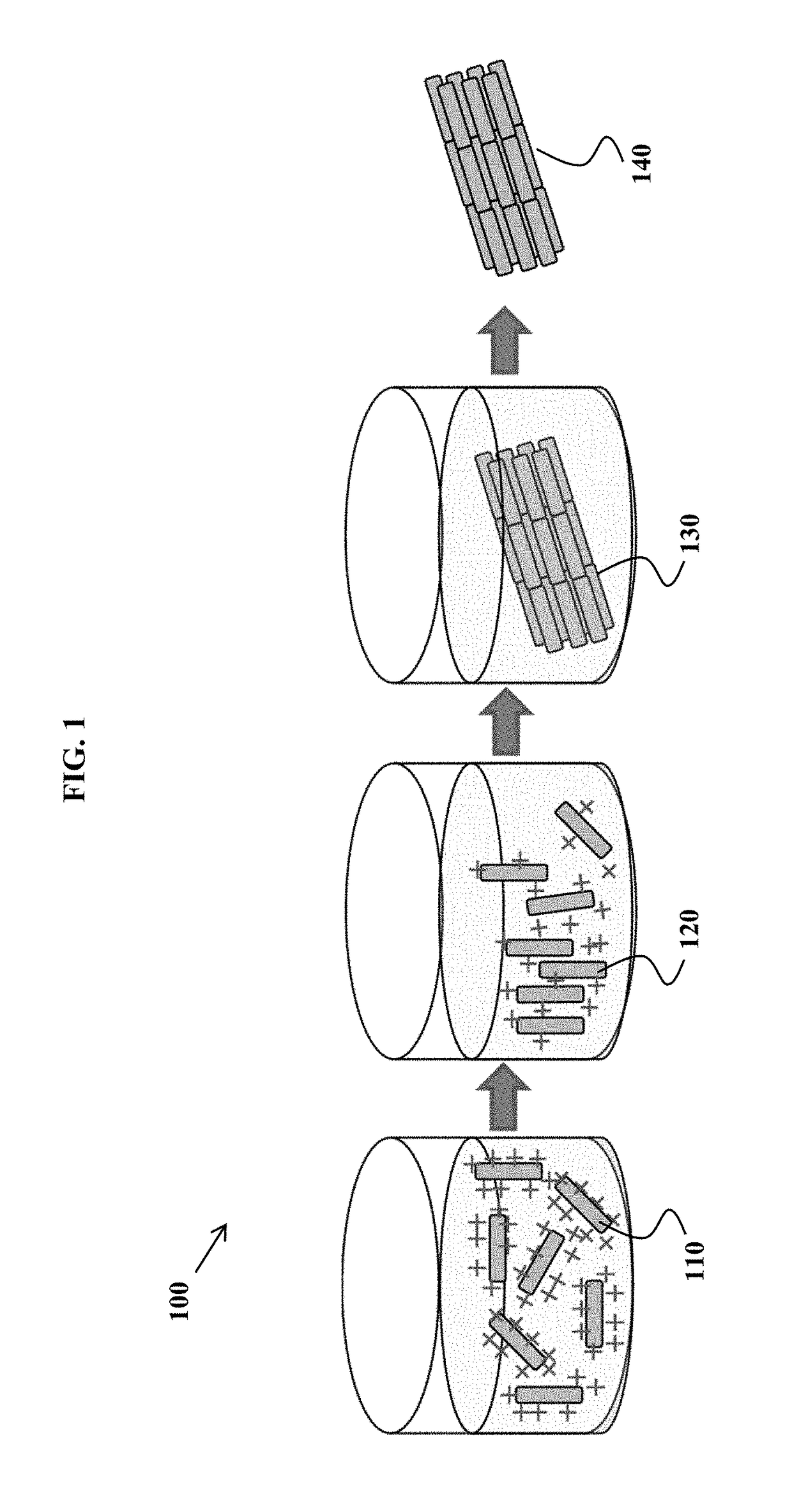
The patent describes a method where two different types of particles are mixed together in a liquid solution. The first particles have a certain charge, while the second particles have a different but lower charge. When the pH of the solution changes, the second particles assemble to form a certain pattern. This method can be used to create certain structures using the particles.

Problems solved by technology

The presence of organic ligands is problematic because the ligands can melt from heat, darken in the presence of light, and inhibit electrical conductivity.
Arrays of nanoparticles from crystallization methods are usually surrounded by organic ligands that interfere with further chemical processing and can limit durability.
Arrays of nanoparticles from crystallization methods are not protected by an outer layer, which makes them susceptible to environmental damage.
This results in a low density of material and reduced efficacy from the array.
The packed arrays of nanoparticles, as taught in the prior art, tend to be non-uniform in array size and shape.

Method used


Image

  • Devices for charge-titrating particle assembly, and methods of using the devices
  • Devices for charge-titrating particle assembly, and methods of using the devices
  • Devices for charge-titrating particle assembly, and methods of using the devices

Examples


example 1

e Nanorods

[0234]In this example, β-FeOOH nanorods are fabricated for later assembly.

[0235]The synthesis of β-FeOOH nanorods occurs by mixing 270 mg of FeCl3.6H2O and 16 mL of water. The resulting transparent orange solution is then sealed in a Teflon-lined 23 mL acid digestion bomb that is subsequently warmed up at a rate of 1.0° C. / min to 120° C. and held for 1 hour in an oven. The reaction bomb is allowed to naturally cool down to room temperature after 1 hour and the resulting brown precipitate is collected with centrifugation. The solids are suspended in water, vortexed, and centrifuged; the supernatant is discarded. This cleaning step is repeated two additional times.

[0236]The material has an isoelectric point of 5.95. The iron oxide nanorods are shown in an SEM image, in FIG. 8.

example 2

ning Iron Oxide Nanorods

[0237]This example describes generation of aluminum-containing iron oxide nanorods for later assembly of the nanorods.

[0238]The synthesis of Al-containing β-FeOOH nanorods occurs by mixing 270 mg of FeCl3.6H2O, 120 mg urea, 43 mg of Al(NO3)3.9H2O, and 16 mL of water. The resulting transparent orange solution is then sealed in a Teflon-lined 23 mL acid digestion bomb that is subsequently warmed up at a rate of 1.0° C. / min to 120° C. and held for 2 hours in an oven. The reaction bomb is then allowed to naturally cool down to room temperature and the resulting brown precipitate is collected with centrifugation. The solids are suspended in water, vortexed, and centrifuged; the supernatant is discarded. This cleaning step is repeated two additional times.

[0239]The material has an isoelectric point of 7.50 showing that Al is present in the iron oxide (aluminum oxides have higher isoelectric points than iron oxides). The Al-containing β-FeOOH nanorods are shown in a...

example 3

of Iron Oxide Nanorods

[0240]In this example, the β-FeOOH nanorods fabricated in Example 1 are assembled into nanorod arrays.

[0241]The product from Example 1 is dispersed in 16 mL of deionized water. 8 mL of the material is separated and the pH is adjusted to 1.6 with 0.5 M HCl. 19 mg urea is added. The resulting suspension is then sealed in a Teflon-lined 23 mL acid digestion bomb that is subsequently warmed up at a rate of 1.0° C. / min to 120° C. and held for 1 hour in an oven. The reaction bomb is allowed to naturally cool down to room temperature.

[0242]The final pH is 6.70. The orange precipitate is collected with centrifugation. The solids are suspended in water, vortexed, and centrifuged; the supernatant is discarded. This cleaning step is repeated two additional times.

[0243]The assembled product is shown in a SEM image, in FIG. 10.


PUM

PropertyMeasurementUnit
particle sizeaaaaaaaaaa
zeta potentialaaaaaaaaaa

Abstract

Methods to fabricate tightly packed arrays of nanoparticles are disclosed, without relying on organic ligands or a substrate. In some variations, a method of assembling particles into an array comprises dispersing particles in a liquid solution; introducing a triggerable pH-control substance capable of generating an acid or a base; and triggering the pH-control substance to generate an acid or a base within the liquid solution, thereby titrating the pH. During pH titration, the particle-surface charge magnitude is reduced, causing the particles to assemble into a particle array. Other variations provide a device for assembling particles into particle arrays, comprising a droplet-generating microfluidic region; a first-fluid inlet port; a second-fluid inlet port; a reaction microfluidic region, disposed in fluid communication with the droplet-generating microfluidic region; and a trigger source configured to trigger generation of an acid or a base from at least one pH-control substance contained within the reaction microfluidic region.

Description

PRIORITY DATA[0001]This patent application is a non-provisional application claiming priority to U.S. Provisional Patent App. No. 62 / 212,969, filed Sep. 1, 2015, and to U.S. Provisional Patent App. No. 62 / 213,044, filed Sep. 1, 2015, each of which is hereby incorporated by reference herein.STATEMENT REGARDING FEDERALLY SPONSORED RESEARCH OR DEVELOPMENT[0002]This invention was made with Government support under DARPA Contract No. FA8650-15-C-7549. The Government has certain rights in this invention.FIELD OF THE INVENTION[0003]The present invention generally relates to structures and materials containing nanostructured assemblies, and methods of fabricating such assemblies.BACKGROUND OF THE INVENTION[0004]Tightly packed, organic-free arrays of nanoparticles are useful for optical, magnetic, and electronic device applications. There are existing approaches for forming packed nanoparticles, employing organic ligands in solution to form assemblies. The presence of organic ligands is prob...

Claims


Application Information

Patent Timeline
Patent Type & Authority Patents(United States)
IPC IPC(8): B01J19/00C01F17/00C30B29/62C30B29/12C30B29/22C01G49/02C30B33/06C01G49/00C30B7/14C30B7/10B01L3/00
CPCB01J19/0046C01G49/02C01G49/0045C01F17/0062C30B7/10C30B7/14C30B33/06C30B29/22C30B29/12C30B29/62B01J2219/00754B01J2219/00331B01J2219/00585B01J2219/00599B01J2219/0075B01J2219/00686C01P2004/16C01P2004/40C01P2004/64C01P2004/62C01P2004/61C01P2004/80B01L3/502784B01L2200/0647B01L2200/0673C30B29/16C30B29/60B82Y40/00C01P2004/03C01P2004/50C01F17/36C01F17/265
Inventor ROPER, CHRISTOPHER SGROSS, ADAM F.
Owner HRL LAB
Learn More