Battery electrode and method for producing same

a battery electrode and electrode material technology, applied in the field of battery electrodes, can solve the problems of complex and expensive production methods of uncoated arrester regions using masking steps or brushing away coatings, and achieve the effect of low production cost and maximum freedom of design

Active Publication Date: 2018-05-08
ZENT FUR SONNENENERGIE & WASSERSTOFF FORSCHUNG BADEN WURTTEMBERG GEMEINNUTZIGE STIFTUNG
View PDF26 Cites 3 Cited by
  • Summary
  • Abstract
  • Description
  • Claims
  • Application Information

AI Technical Summary

Benefits of technology

[0014]The object of the present invention is therefore to specify a battery electrode and a production method for said battery electrode which allow for maximum freedom of design when configuring an arrester region and a battery electrode at low production costs.
[0016]The invention is based on the idea of removing a coating film, formed on a collector substrate, in an arrester region by laser ablation. In this way, the coating film can be produced over a large surface area and continuously on the collector substrate without an arrester region having to be kept open. Owing to the uniform thickness of the areally coated collector substrate, a calendering process is further simplified and can be carried out with better quality. In addition, any desired electrode shape can be cut from the coated collector substrate without being restricted by a predefined position of the arrester region. Consequently, the electrode material can be utilized more efficiently so that less waste material is produced. On account of using a laser to expose the arrester regions, the arrester regions can also be produced on the coated collector substrate in any desired shape and at any desired position with clean and regular edges. This provides absolute freedom of design and the option of producing arrester structures which are optimized in respect of surface area. By way of example, inactive regions on the electrode, i.e. the surfaces of the arrester regions, can be reduced. An inactive volume in the battery can thus also be reduced, e.g. by uncoated arrester regions projecting inwardly into a coated region of the electrode or being formed within the coated regions. Alternatively, at least half a circumference of the arrester region can be surrounded by the coated region.
[0017]Any suitable laser system, for example cutting or engraving laser systems, can be used for removing the material by means of laser ablation. On account of the high edge quality and cutting precision in respect of cut guidance and penetration depth, high-quality arrester regions can be produced. Furthermore, by virtue of the use of ultra-short laser pulses, the energy input can be reduced, with the result that thermal loading of the electrode material is kept low. Since suitable laser systems are comparable to slot die systems in respect of cost, high purchase costs are not incurred.
[0018]According to one aspect of the present invention, a method for producing a battery electrode is specified. In this method, a coating film is first applied on a collector substrate. The coating film is then removed using a laser in at least one arrester region. This can be performed by pulsed laser radiation or continuous laser radiation. The coating film is possibly formed on both sides of the collector substrate in order to increase the size of an active surface of the electrode. At least one arrester region can then be formed on the two sides of the collector substrate in each case. In addition, the coating film can be formed such that it substantially completely covers at least one of the two surfaces of the collector substrate, without leaving free edges or free regions uncoated. For coating purposes, a continuous coating method, for example doctor blade, comma bar or kiss coating, is preferably used. As a result, a greater degree of processing reliability and therefore a better quality of the electrode material can be ensured at low production costs.
[0019]In a further exemplary embodiment, it is not only the coating film that is removed using a laser in an arrester region, but a thin layer on the surface of the collector substrate is also removed, with the result that a fresh, clean surface is produced. As a result, impurities and oxidized layers in the arrester region can be removed, as a result of which contact resistance between the electrodes and a connection lug is reduced. The connection lug is preferably attached to the arrester region immediately after the arrester region is produced, wherein the production of the arrester region can comprise either only the removal of the coating film or the removal of the coating film and of a surface layer of the collector substrate. Therefore, the occurrence of impurities can be avoided, it being possible for these impurities to present a serious danger to a finished battery and cause the formation of dendrites with the resulting short circuit, for example abrasive particles or coating residues which are produced during brushing, by using a laser for removing the coating film and / or a surface layer of the collector substrate.
[0020]In a preferred embodiment of the method according to the invention, the battery electrode is cut out in a predefined shape with the aid of the laser either before or after the at least one arrester region is produced. In this way, any desired electrode shape can be selected, without special tools, for example particular stamping dies, having to be created. As a result, the freedom of design when producing the battery electrode is further increased and the operating procedure is optimized. The working time and an additional tool can be saved by forming the arrester region and cutting out the battery electrode by means of laser since changing over of the electrode material which is to be processed and of the tool is dispensed with. Therefore, the arrester region, or else the battery electrode, can be produced in any desired shape, for example round, semicircular, annular, rectangular or triangular. In addition, the arrester region can be arranged on the coated electrode surface in any desired manner. The arrester region preferably projects into the coated electrode surface such that a relatively large portion of its circumference, or at least half of it, is surrounded by the coated electrode surface. In this case, the remaining portion of the circumference of said arrester region can adjoin an outer edge of the battery electrode. As an alternative, the arrester region can be arranged entirely within the coated electrode surface. In this way, an inactive region or dead volume can be reduced when the battery is assembled, with the result that a capacity and a volumetric energy density is increased given the same battery size.

Problems solved by technology

However, forming relatively complex arrester regions using these methods is very complicated.
However, the following problems are encountered in the conventional methods for producing battery electrodes.
For example, the production of uncoated arrester regions by masking steps or brushing away the coating is very complex and expensive.
In the alternative production method by intermittent or continuous coating with the aid of a slot die system however, the possible shapes and arrangements of the arrester regions on the electrode material are greatly restricted.
In this case, the trend toward relatively small devices poses a particular challenge to battery production.
Firstly, batteries with relatively small dimensions therefore have to be developed, and secondly complex shapes are often required in order to make the most efficient use of the interior of a device as possible.
Furthermore, it is difficult to produce regular and clean edge regions between the coating region and the arrester region in the case of an intermittent coating method.
Furthermore, it is difficult and expensive to realize a variety of shapes of the electrodes with the conventional methods.
As a result however, the degree of freedom of design for the electrode shape is severely restricted because each electrode has to have an arrester region 40.
As a result, material consumption is increased and the production method is more expensive.
However, these stamping dies are very expensive on account of the high demands made on cutting quality.
However, this leads to unutilized space in the battery which is not filled with active electrode material.
As a result, the size of the battery is unnecessarily increased and / or an outer shape of the battery is fixed.
Furthermore, the arrester regions 40 can be easily contaminated in the conventional production methods or else during storage.
This has an adverse effect on the quality of an electrical contact between electrodes of the same kind and between the electrodes and an associated connection lug 50.
Since the arrester regions 40 are additionally formed before the calendering process during production of the electrode material, calendering is made more difficult on account of the non-uniformly thick structure.
In addition, the arrester region 40 which is formed by conventional methods may be poorly defined, wherein particularly an edge region of the arrester region 40 can be formed in an inaccurate and non-uniform manner.

Method used


Image

  • Battery electrode and method for producing same
  • Battery electrode and method for producing same
  • Battery electrode and method for producing same

Examples


Embodiment Construction

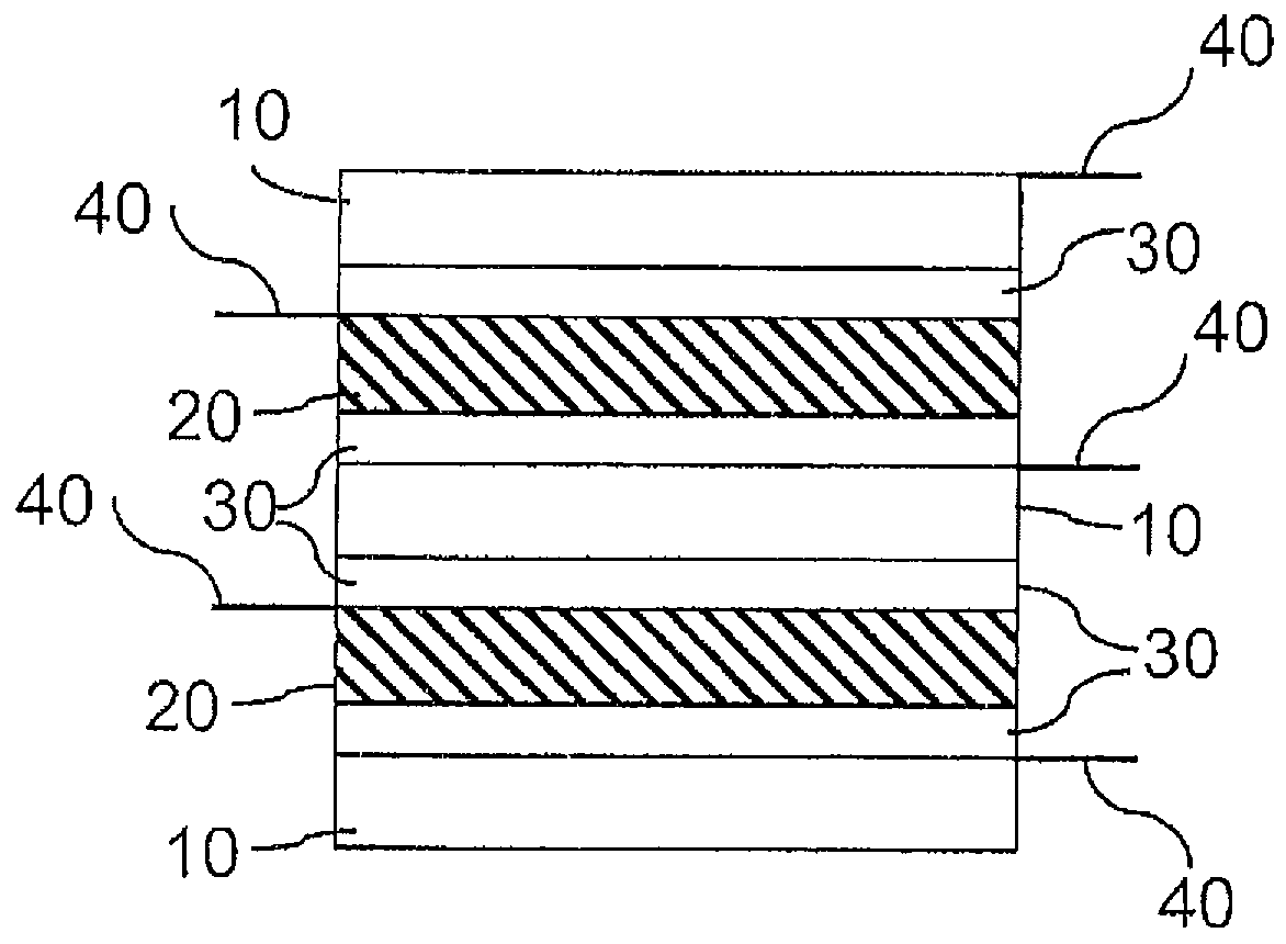
[0036]The invention will be described below using the example of the lithium-ion battery which is distinguished by a high energy density and thermal stability. However, the present invention is not intended to be restricted to lithium-ion batteries but can be applied to any desired battery.

[0037]In a lithium-ion battery, a collector substrate 60 of an anode 10 is composed, for example, of copper which is coated with a coating film 70 which is composed of graphite, binder, carbon black and solvent. According to the present invention, the coating film 70 in an arrester region 40 is removed, with the result that the collector substrate 60 in the arrester region 40 is exposed. A connection lug 50, which is composed of nickel, can be mounted on the arrester region 40 of the anode 10. In the case of the cathode 20, a collector substrate 60 is composed, for example, of aluminum and is coated with a coating film 70 comprising an active material which contributes to a redox reaction, binder,...


PUM

PropertyMeasurementUnit
thicknessaaaaaaaaaa
wavelengthaaaaaaaaaa
thickaaaaaaaaaa

Abstract

In order to allow for maximum freedom of design in the selection of an electrode or battery shape, a compact configuration and low production costs, the invention specifies a battery electrode and a method for producing same, wherein a collector substrate is coated with a coating film and at least one arrester region is produced thereon by removing the coating film by means of laser ablation.

Description

CROSS-REFERENCE TO RELATED APPLICATIONS[0001]This application claims priority to International Patent Application No. PCT / EP2011 / 005945 filed Nov. 25, 2011, which claims priority to German Patent Application No. 10-2010-062-140.4, filed Nov. 29, 2010.TECHNICAL FIELD[0002]The invention relates to a battery electrode and to a method for producing same.BACKGROUND TO THE INVENTION[0003]In general, a battery indicates both non-rechargeable primary cells and rechargeable secondary cells (also called rechargeable batteries). Batteries are classified on the basis of the underlying chemical redox reaction, the materials used, the electrical values (for example voltage or capacitance) or the geometric or structural design. Examples include alkaline-manganese batteries, zinc-carbon batteries or lithium batteries. A distinction is also drawn between winding cells and stacked batteries in batteries, depending on their inner construction. In the case of a winding cell, the electrode and separator...

Claims


Application Information

Patent Timeline
Patent Type & Authority Patents(United States)
IPC IPC(8): H01M4/70H01M4/04H01M2/26H01M10/04H01M10/0585H01M4/02B23K26/40H01M10/052B23K101/34H01M50/533H01M50/534H01M50/536
CPCH01M4/0435B23K26/40H01M2/26H01M4/02H01M4/0402H01M4/70H01M10/04H01M10/0585B23K2201/35H01M10/052Y10T29/49115H01M50/536H01M50/533H01M50/534B23K2101/35Y02E60/10Y02P70/50H01M4/0404H01M4/0471H01M50/531
Inventor STERN, RAINERKASPER, MICHAEL
Owner ZENT FUR SONNENENERGIE & WASSERSTOFF FORSCHUNG BADEN WURTTEMBERG GEMEINNUTZIGE STIFTUNG
Why Eureka
Try Eureka