Ring antenna array element with mode suppression structure

a phase suppression structure and antenna array technology, applied in the direction of individual energised antenna arrays, resonant antennas, antenna couplings, etc., to achieve the effect of reducing cross-coupling

Active Publication Date: 2018-03-06
THE BOEING CO
View PDF29 Cites 1 Cited by
  • Summary
  • Abstract
  • Description
  • Claims
  • Application Information

AI Technical Summary

Benefits of technology

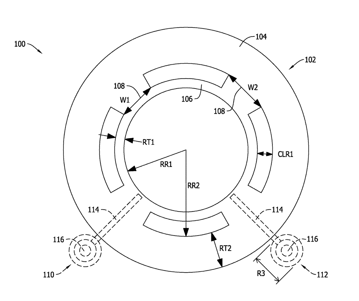
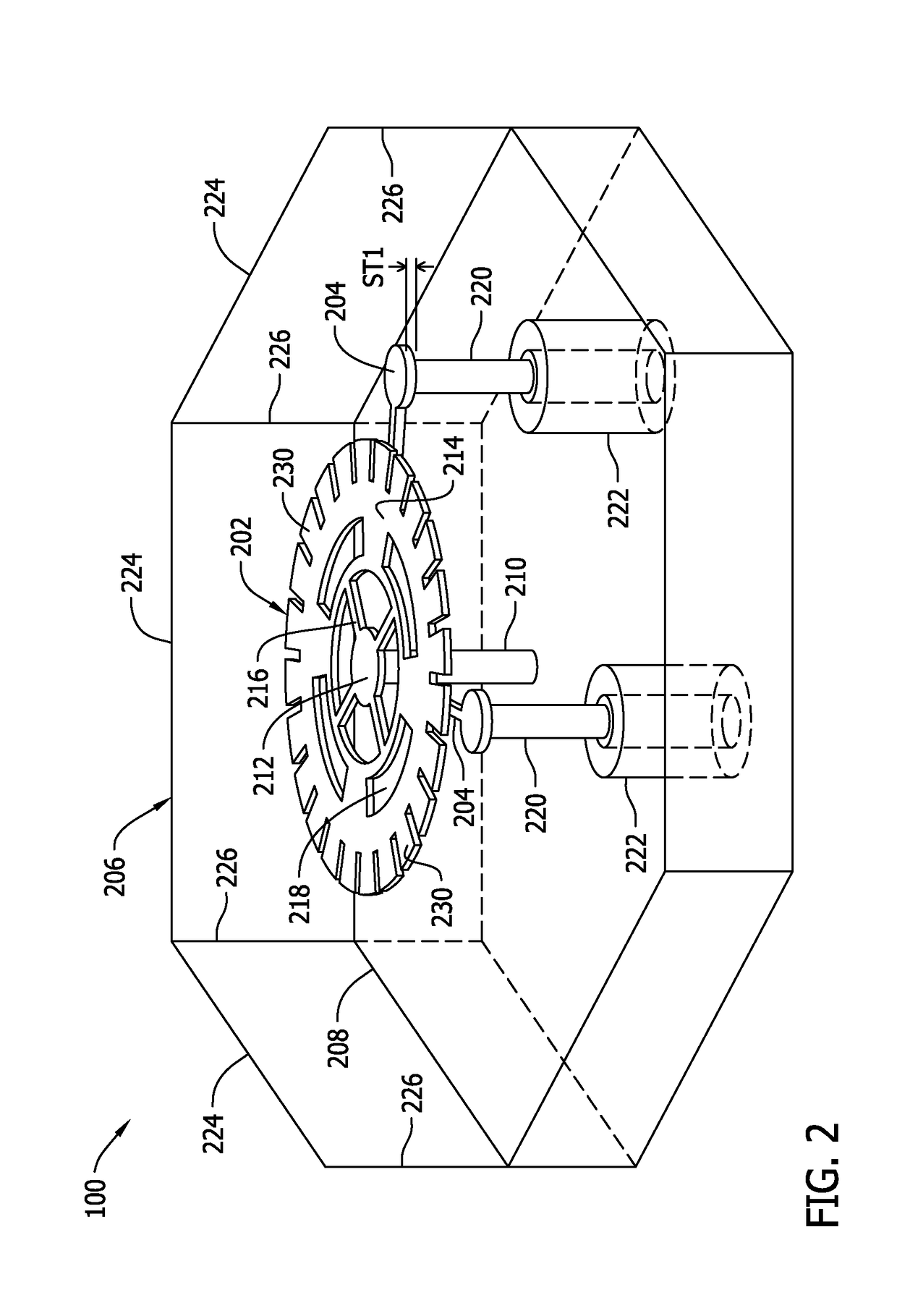
[0004]According to one aspect of the present disclosure, a radio frequency circuit for a ring antenna array element is provided. The radio frequency circuit includes first and second feed elements, and a conductive element disposed between the first and second feed elements. The first and second feed elements are electrically couplable to a conductive resonator for a frequency band. The first feed element is configured to conduct an electromagnetic current. The conductive element is configured to resonate outside the frequency band to reduce cross-coupling between the first feed element and the second feed element due to the electromagnetic current.

Problems solved by technology

Current microwave and millimeter-wave frequency antennas generally include cumbersome structures such as waveguides, dish antennas, helical coils, horns, and other large non-conformal structures.

Method used


Image

  • Ring antenna array element with mode suppression structure
  • Ring antenna array element with mode suppression structure
  • Ring antenna array element with mode suppression structure

Examples


Embodiment Construction

[0015]As used herein, an element or step recited in the singular and proceeded with the word “a” or “an” should be understood as not excluding plural elements or steps unless such exclusion is explicitly recited. Furthermore, references to “one embodiment” of the present invention or the “exemplary embodiment” are not intended to be interpreted as excluding the existence of additional embodiments that also incorporate the recited features.

[0016]In certain applications, conformal phased array antennas require wide frequency coverage and large scan volumes. For example, certain SATCOM systems cover a commercial band of 17.7-20.2 Gigahertz (GHz) and a military band of 20.2-21.2 GHz, and also scan up to 60 degrees from boresight. In another example, certain SATCOM systems operate in the 27.5-31 GHz band and the 43.5-45.5 GHz band. These systems are referred to as dual-band.

[0017]Dual-band applications typically utilize either multiple phased array antennas or dual-band dish antennas und...


PUM


Abstract

A radio frequency (RF) circuit for a ring antenna array element includes first and second feed elements, and a conductive element disposed between the first and second feed elements. The first and second feed elements are electrically couplable to a conductive resonator for a frequency band. The first feed element is configured to conduct an electromagnetic current. The conductive element is configured to resonate outside the frequency band to reduce cross-coupling between the first feed element and the second feed element due to the electromagnetic current.

Description

INCORPORATION BY REFERENCE[0001]U.S. patent application Ser. No. 13 / 476,953 filed May 21, 2012 titled “Cog Ring Antenna for Phased Array Applications,” is incorporated herein by reference in its entirety.BACKGROUND[0002]The field of the disclosure relates generally to ring antennas for phased arrays, and more specifically to controlling cross-coupling using a mode suppression structure.[0003]Current microwave and millimeter-wave frequency antennas generally include cumbersome structures such as waveguides, dish antennas, helical coils, horns, and other large non-conformal structures. Communication applications, where at least one communicator is moving, and radar applications generally require a steerable beam or steerable reception. Phased array antennas are particularly useful for beam steered applications since beam steering can be accomplished electronically without physical motion of the antenna. Electronic beam steering can be faster and more accurate and reliable than gimbale...

Claims


Application Information

Patent Timeline
Patent Type & Authority Patents(United States)
IPC IPC(8): H01Q13/12H01Q1/52H01Q9/04H01Q21/06H01Q3/30
CPCH01Q1/523H01Q9/0421H01Q9/0435H01Q9/0457H01Q9/0442H01Q21/065H01Q3/30
Inventor MANRY, JR., CHARLES W.
Owner THE BOEING CO
Why Eureka
Try Eureka