Devices and methods for spatial filtering

a technology of spatial filtering and filters, applied in the direction of instruments, optical waveguide light guides, optical light guides, etc., can solve the problems of undesirable coupling, achieve the effects of improving the extinction ratio of the substrate, reducing the cross-coupling of unwanted modes of light, and improving the extinction ratio

Active Publication Date: 2010-05-04
HONEYWELL INT INC
View PDF6 Cites 3 Cited by
  • Summary
  • Abstract
  • Description
  • Claims
  • Application Information

AI Technical Summary

Benefits of technology

[0006]The invention provides a proton exchange polarizer where cross-coupling of unwanted modes of light is reduced with an integrated spatial filter. An optically transmissive substrate such as a substrate created from LiNbO3 or LiTaO3 has side surfaces which reflect unguided TM mode light. The light originates from an input fiber. The input fiber is connected to the substrate at one end and an output fiber is connected to receive guided TE mode light at the opposite end. The sides of the substrate couple the unguided TM mode light to the output fiber. This coupling is undesirable in various polarizer applications such as those used in fiber-optic gyros. The extinction ratio of the substrate is improved by the incorporation of a spatial filter. The spatial filter is positioned at the primary reflection position of the light with respect to the sides of the polarizer. To improve extinction further, the spatial filter can also be located at secondary reflection points in another alternate embodiment. The spatial filter is positioned within the substrate or at the sides of the substrate, depending on whether the barrier was created by physical or chemical methods such as saw cutting, etching, diamond machining, micro-machining, or laser-machining. The spatial filter acts to block the propagation of the unguided TM light.

Problems solved by technology

This coupling is undesirable in various polarizer applications such as those used in fiber-optic gyros.

Method used


Image

  • Devices and methods for spatial filtering
  • Devices and methods for spatial filtering
  • Devices and methods for spatial filtering

Examples


Embodiment Construction

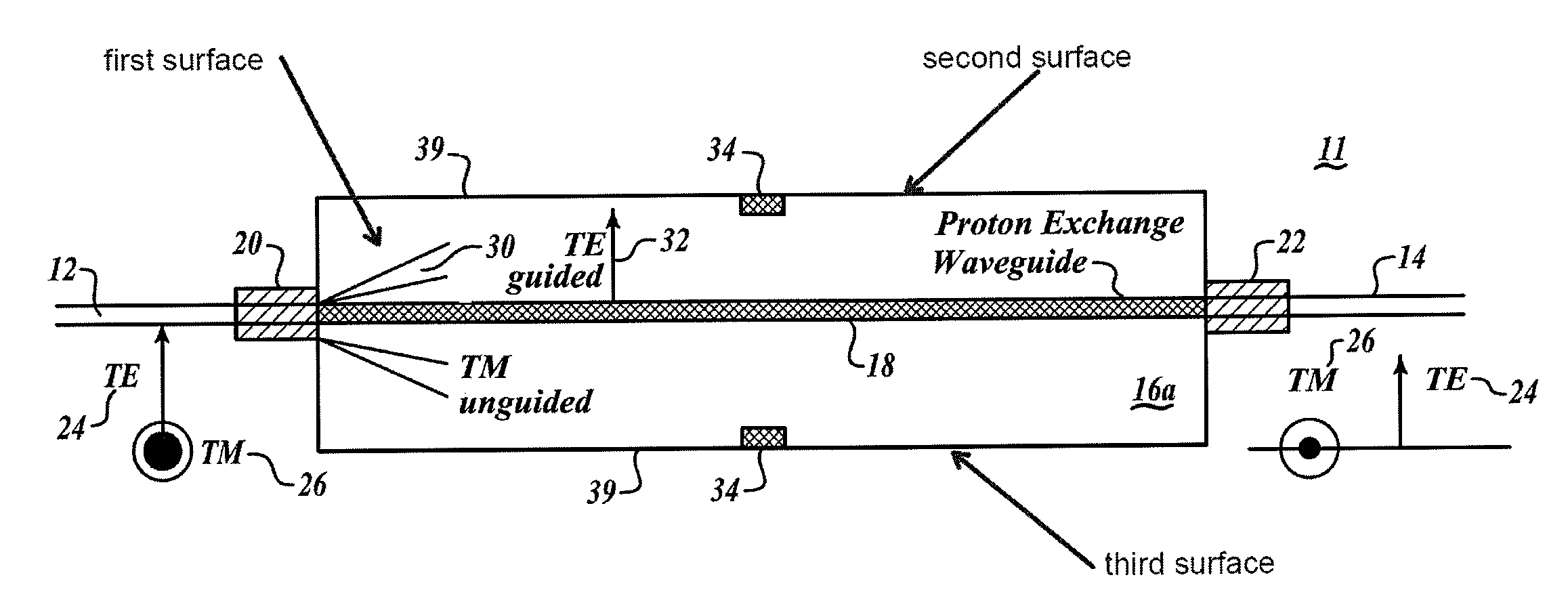
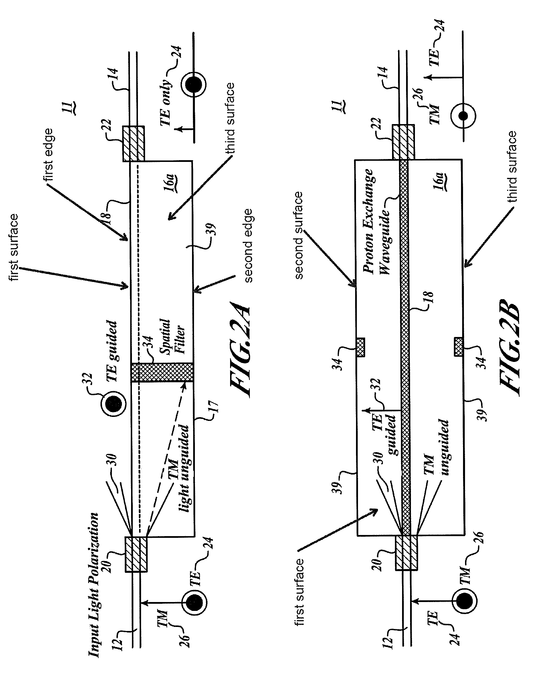
[0015]FIGS. 2A, B show a proton exchange polarizer 11 with an integrated spatial filter 34 located in the substrate 16a. The substrate 16a couples a fiber 12 with ferrule 20 to fiber 14 to ferrule 22. The substrate 16a incorporates a proton exchange wave guide 18. The TM mode unguided light 30 propagates through the light conducting substrate 16a but is blocked by spatial filter 34 incorporated into the substrate 16a. The spatial filter 34 prevents reflected light from coupling back into the output fiber 14 by blocking the propagation of the light wave. The barrier, or the spatial filter 34, may be advantageously made by a number of processes including physically depositing the spatial filter 34 into the substrate 16a. The substrate may be saw-cut to create a void in the substrate 16a impeding the propagation of the unguided TM mode light 30. The side may be diamond machined, etched, micro-machined or laser-machined. Alternatively, the surface may simply be scratched or similarly da...


PUM


Abstract

Methods and devices for polarizing light in a proton exchange polarizer where cross-coupling of unwanted modes of light is reduced with an integrated spatial filter. An optically transmissive substrate such as a substrate created from LiNbO3 or LiTaO3 has side surfaces, which reflect unguided TM mode light. The light originates from an input fiber. The input fiber is connected to the substrate at one end and an output fiber is connected to receive guided TE mode light at the opposite end. The spatial filter is positioned at the primary reflection position of the light with respect to the sides of the polarizer. To improve extinction further, the spatial filter can also be located at secondary reflection points in another alternate embodiment.

Description

BACKGROUND OF THE INVENTION[0001]Optical wave guide devices fabricated by the Proton Exchange (PE) method provide some unique qualities. The process of proton exchange increases the refractive index only in extraordinary axis and thus will only guide one polarization state. The other polarization state is unguided and is eventually eliminated. This quality of Proton Exchange devices makes them naturally very high performance polarizers (60 dB or more). In addition, this quality makes them very attractive for use in Multiple Function Chips (MFCs) used in construction of fiber optic gyros (FOGs).[0002]Now refer to FIG. 1A which shows a schematic diagram of a proton exchange polarizer with crosstalk. A proton exchange polarizer 10 includes a LiNbO3 or LiTaO3 material forming an optically transmissive substrate 16. The proton exchange polarizer 10 further includes a glass ferrule 20 as an input coupling for an optical fiber 12 and a glass ferrule 22 coupled to an output fiber 14. The op...

Claims


Application Information

Patent Timeline
Patent Type & Authority Patents(United States)
IPC IPC(8): G02B6/00G02B6/14
CPCG02B6/1345G02B6/126
Inventor LEWIS, JEFFREY E.
Owner HONEYWELL INT INC
Why Eureka
Try Eureka