Waveguide element and waveguide stack for display applications

Pending Publication Date: 2021-04-15
DISPELIX OY
View PDF0 Cites 2 Cited by
  • Summary
  • Abstract
  • Description
  • Claims
  • Application Information

AI Technical Summary

Benefits of technology

The invention aims to reduce cross-coupling and improve the efficiency of using waveguides in display devices. It introduces a selective in-coupler that allows for the realization of high-quality multi-color displays with a large field of view. By preventing cross-coupling between layers, it achieves better visual quality while maintaining the necessary color representation.

Problems solved by technology

Typically, surface relief gratings are not very polarization sensitive over a large field of view (FOV) which causes cross-coupling between the plates and leads to color variations over a uniform white image.
Some conventional in-coupling solutions also require a relatively large area on the waveguide and / or set some undesired restrictions on the form factor of the waveguide, limiting their use in practical applications.

Method used


Image

  • Waveguide element and waveguide stack for display applications
  • Waveguide element and waveguide stack for display applications
  • Waveguide element and waveguide stack for display applications

Examples


Embodiment Construction

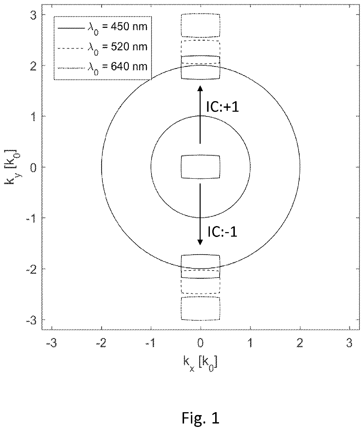
[0022]In one embodiment, the present approach comprises uniquely in-coupling only wavelengths below a threshold value using an in-coupler that splits FOV into two parts by + / −1st diffraction orders and exhibits such a small grating period that wavelengths above the threshold value experience only the zeroth order diffraction.

[0023]This is illustrated in FIG. 1 that shows the wave vector analysis for the in-coupling grating that has a grating vector parallel to the y-axis. It is assumed that the lightguide has refractive index of 2.0, it resides in the xy-plane, and the virtual image has 52 deg diagonal FOV with 16:9 aspect ratio. The + / −1st orders moves the FOV box from the center into the annulus. The inner radius of annulus is defined by the refractive index of air (=1.0) and the outer radius by the refractive index of the waveguide (=2.0). The FOV points inside the annulus propagate via total internal reflection inside the waveguide. The FOV points outside the annulus are forbidd...


PUM


Abstract

The invention relates to a waveguide display element comprising a waveguide body and an in-coupling grating (21) arranged to the waveguide body. The in-coupling grating (21) is configured to couple incoming light into the waveguide body into two separate directions (26A, 26B) using opposite diffraction orders (IC:+1, IC:−1) for splitting the field of view of the incoming light. Further the in-coupling grating (21) is configured, typically by setting its period suitably short, such that said coupling takes place only at wavelengths below a threshold wavelength residing in the visible wavelength range. The invention also relates to a waveguide stack (51 A, 51 B, 51 C).

Description

FIELD OF THE INVENTION[0001]The invention relates to waveguide-based displays. In particular, the invention relates to a light in-coupling arrangement for use in such displays. The invention can be used in modern personal displays, such as head-mounted displays (HMDs) and head-up displays (HUDs).BACKGROUND OF THE INVENTION[0002]To maximize the field of view of see-through augmented reality (AR) displays based on diffractive waveguides, a common approach is to use multiple waveguides stacked on top of each other. To make the optimization process manageable, it is desirable that each lightguide in-couples only a single wavelength (e.g. laser light) or a narrow wavelength band (e.g. spectrum of a single color led). Some approaches based on polarization has been presented earlier, e.g. in US 2014 / 0064655 A1. Typically, surface relief gratings are not very polarization sensitive over a large field of view (FOV) which causes cross-coupling between the plates and leads to color variations ...

Claims


Application Information

Patent Timeline
IPC IPC(8): G02B27/00G06F1/16G02B6/293
CPCG02B27/0081G02B27/0172G02B6/29323G06F1/1607G02B27/4272G02B2027/0174G02B27/1006G02B27/1086G02B6/0076G02B5/1823G02B5/1842G02B5/1861G02B27/4205
Inventor BLOMSTEDT, KASIMIROLKKONEN, JUUSO
Owner DISPELIX OY
Why Eureka
Try Eureka