
Background removal from Raman spectra by an intracavity active-tuning element for a laser

a technology of active tuning element and background removal, which is applied in the field of chemical detection utilizing raman spectroscopy, can solve the problems of limiting the performance of raman spectroscopy, high cost and impracticality, and complicated design, and achieves simple, effective, compact and economical multiple wavelength raman spectra acquisition, and improves detection performance. performance, the effect of improving the detection performan

Active Publication Date: 2018-02-27
ALAKAI DEFENSE SYST
View PDF27 Cites 5 Cited by
  • Summary
  • Abstract
  • Description
  • Claims
  • Application Information

AI Technical Summary

Benefits of technology

The present invention is about systems, apparatus, and methods for multiple wavelength Raman spectra acquisition. The invention solves problems and deficiencies in the art by using a single non-diode laser source and a laser intracavity tuning element or subsystem to generate plural laser wavelengths. This avoids the need for a separate laser source, complex components or controls, resource intensive calibration, or extreme precision and accuracy in operation for effectiveness. The invention allows implementation in a variety of configurations, including a single instrument, and can improve detection performance relative to Raman information. The tuning element can take different forms, such as plural sets of a fixed cavity end mirror and etalon or control of acousto-optic modulators, Pockels cells, or spinning reflectors to select between alternative sets of mirror / etalon combinations. The invention also includes techniques to synchronize or correlate the laser interrogation with the spectral acquisition and to process the acquired information to extract the Raman data over a significant gain bandwidth to improve detection performance.

Problems solved by technology

But additional factors can complicate such design.
Some laser sources are tunable but not over a large bandwidth, This limits its performance regarding Raman spectroscopy.
It is possible to add somewhat complex components including multiple lasers to get different laser wavelengths, as exemplified in US Pat. No. 7,245,369, incorporated by reference herein, but this can be expensive and impractical.
Therefore, the factors regarding how a laser source can be tuned over effective and efficient bandwidth by relatively noncomplex techniques are not necessarily straightforward because of competing and sometimes antagonistic factors involved.
Many of the systems proposed in the state of the art do not meet these tests.
Others utilize relatively expensive components.
However, satisfactory techniques for tuning a laser over a satisfactory gain bandwidth have not been identified in the art.

Method used


Image

  • Background removal from Raman spectra by an intracavity active-tuning element for a laser
  • Background removal from Raman spectra by an intracavity active-tuning element for a laser
  • Background removal from Raman spectra by an intracavity active-tuning element for a laser

Examples


example 1

[0044

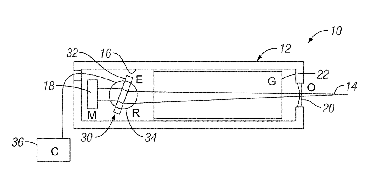
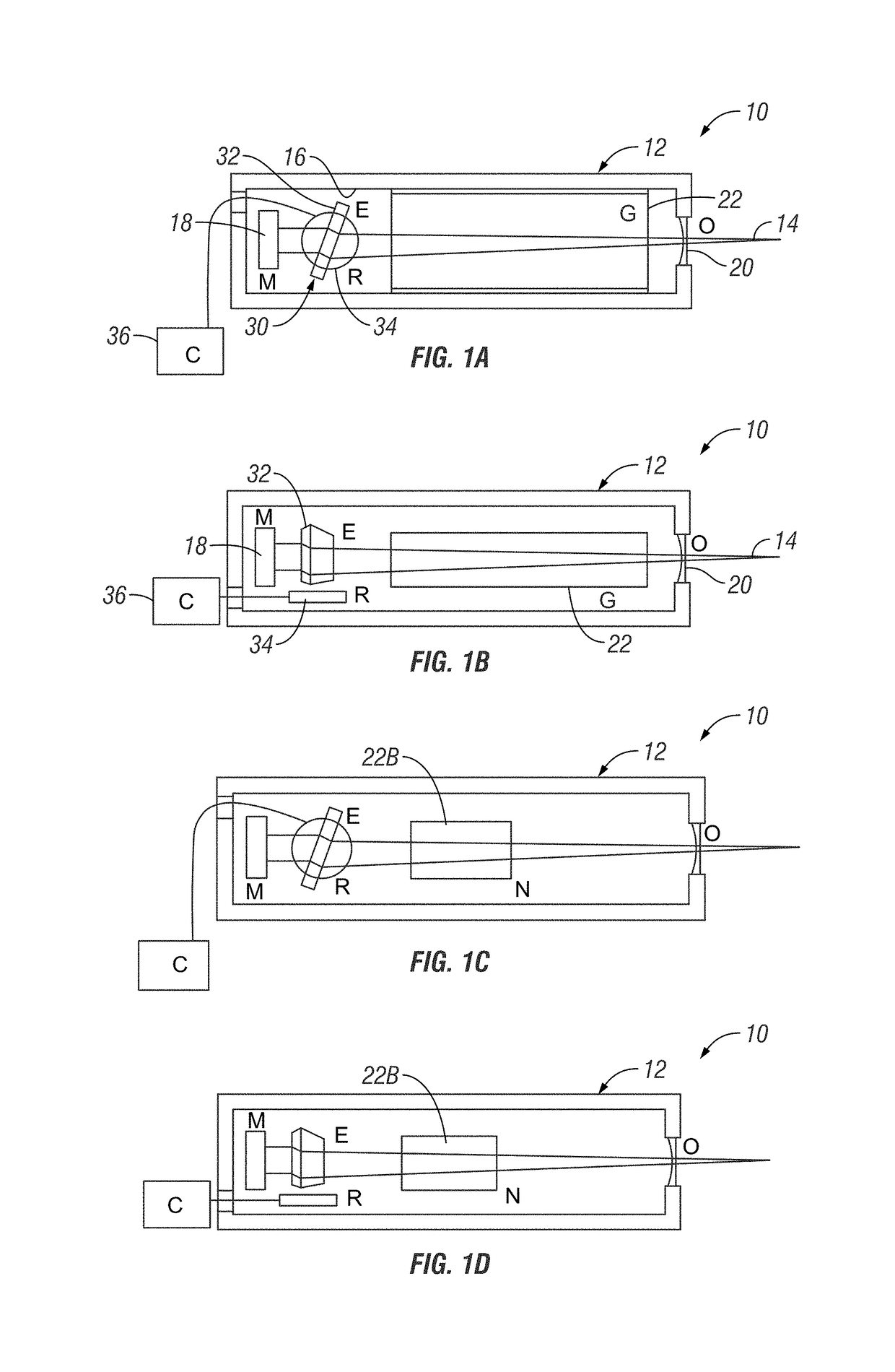
[0045]In the present invention, multiple-wavelength Raman spectra are collected via a single non-laser diode instrument equipped with a tuning element inside the laser cavity. Examples of this invention are shown in FIGS. 1A-D, in which the laser may be either a gas or solid-state laser, such as are well-known to those skilled in this technology and commercially available from a variety of commercial sources.

[0046]In Figures lA and B, a first exemplary embodiment of a laser generation instrument 10 includes a conventional laser cavity 12 from which is developed a laser beam 14. As is further typical, the interior 16 of cavity 12 includes a gain medium 22 between a fixed mirror 18 and an output coupler 20 on opposite sides of gain medium 22. By well-known techniques, excitation energy from an energy source (not shown) is applied to gain medium 16. Light energy is produced that basically bounces back and forth between fixed mirror 18 and the mirror component of output coupler / mir...

example 2

[0059

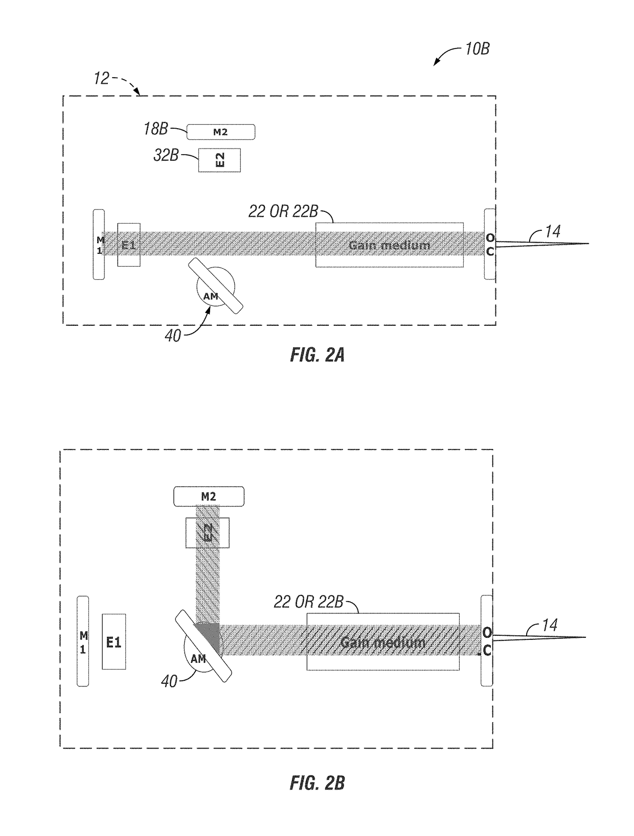
[0060]An additional implementation, shown in FIGS. 2A and B, utilizes a modulator 40 to rapidly switch between two laser cavity end mirrors 18 and 18B with line narrowing elements, such as an étalon 32 and 3213 associated with each end mirror 18 and 18B. Instead of interposing a switchable or controllable element along a single optical path, as in FIGS. 1A-D, this embodiment. instead essentially switches between two alternative optical path sections between a cavity end mirror and the gain medium. The first optical path section (between gain element 22 and mirror 18 / etalon 32) is basically like in FIGS. 1A-D. The components would be selected and configured to generate a first state or laser output wavelength. The modulator 40 would be actuated to a position outside the optical path.

[0061]The second state, generating a second laser output wavelength, is effectuated by movement of modulator 40 into the optical path. This intercepts the laser energy and diverts it to the alternati...

example 3

[0065

[0066]In addition to the hardware configurations of Examples 1 and 2, the following hardware configurations are also envisioned for implementing intracavity laser tuning with or without the signal processing concepts discussed immediately above.

[0067]An acousto-optic modulator 40B is used to refract the cavity by an angle, theta or θ, allowing for rapid switching of wavelength by selecting a different narrowed cavity. (See FIG. 4). Such modulators are commercially available. One is discussed in G. D. Baldwin, Output power calculations for a continuously pumped Q-switched YAG:Nd3+ laser, IEEE J. Quantum Electronics, QE-7, 715, 1971, which is incorporated by reference herein. This is a variation on allowing switching between two laser wavelength states. The basic principle of such modulators uses the acousto-optic effect to diffract and shift the frequency of light using sound waves (e,g. at radio frequency). One configuration uses a piezoelectric transducer attached to a materia...


PUM


Abstract

A system, apparatus, and method for multiple wavelength Raman interrogation laser generation and Raman spectra acquisition. An intracavity laser tuning subsystem is integrated into the laser cavity. The tuning subsystem allows switching between at least two laser output frequencies in a manner effective for good identification and separation of Raman spectra from non-Raman spectra, including auto-fluorescence from the sample and background. The tuning subsystem can be implemented in different ways in the cavity. It does not require material alteration of the line-narrowing components. Also, processing of acquired raw signal from the multiple wavelength interrogation can further assist effective Raman spectra identification and separation.

Description

CROSS-REFERENCE TO RELATED APPLICATIONS[0001]This application claims the benefit of and priority under 35 U.S.C. § 119 to provisional application Ser. No. 61 / 980,902, filed Apr. 17, 2014, incorporated by reference herein in its entirety.BACKGROUND OF THE INVENTION[0002]Field of Invention[0003]The present invention relates to chemical detection utilizing Raman spectroscopy, including but not limited to military use and, in particular, to apparatus and methods for efficiently interrogating a sample (e.g. solids, liquids, solutions, mixtures) at different laser wavelengths to allow acquisition of multiple Raman spectra from the sample to assist in separating Raman information about the sample from background signal, including fluorescence excited by the laser.[0004]Related Art[0005]The value of Raman spectroscopy for an ever-increasing variety of applications is widely discussed in the literature. One example is non-destructive detection of one or more chemical constituents of potentia...

Claims


Application Information

Patent Timeline
IPC IPC(8): H01S3/106H01S3/107H01S3/1055H01S3/08G01N21/65
CPCH01S3/1062H01S3/0809H01S3/1055H01S3/1068H01S3/107G01N21/65G01J3/44H01S3/08054H01S3/0823H01S3/105H01S3/025G01J3/08G01J3/10G01J2003/4424G01J3/0224
Inventor POHL, KENKING, MATTHEWHOPKINS, ADAM J.FORD, ALAN
Owner ALAKAI DEFENSE SYST
Learn More